![]()
Note: The only object that does not appear in the object Explorer is the This Display object. For more information, refer to The This Display Object.
An object is any feature you add to or create in a GraphWorX64 display that has one or more properties, and can be named. Objects can be shapes, layers, primitives, groups, panels, viewers, symbols, PushPins, SmartPins, video controls, pipe controls, scale controls, and other things you can add to a GraphWorX display. All objects appear in the object Explorer. Their properties can be modified. You can also Edit Local Aliases within the object; right-click the object to display the menu and select Edit Local Aliases.
|
|
Note: The only object that does not appear in the object Explorer is the This Display object. For more information, refer to The This Display Object. |
To view the object Explorer:
To view the object Explorer, click the 2D ribbon's View tab and put a check mark in the Explorer check box in the Show/Hide section. Then click the Explorer tab.
Objects can appear in view in the design surface, or they can be hidden from view by being covered by another object, by being in another layer, or by having their visible property set to hidden. Objects must be selected to be modified, but an object can be locked to prevent it from being altered even if it is selected. Some of the basic operations that you can perform with objects are selecting the object, and manipulating the object. How you do this can depend on whether the object is a 2D or 3D object:
The remainder of this topic describes how to select a 2D object, and move, skew, or rotate a 2D object.
To perform the same tasks for a 3D object, you would have to following the instructions in Selection Mode Section of the 3D Home Ribbon and Manipulator Section of the 3D Home Ribbon.
Throughout GraphWorX, how you do something may depend on whether you are working in a 2D or 3D context.
Other topics:
Adding a Glow, Shadow, Blur, or Opacity Effect
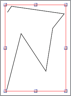
Before you can modify an object, first you need to select it. A selected object displays selection handles that indicate the vertexes and line midpoints of the shape's bounding box.
In 2D displays, selection can be performed with either the mouse, using any of the techniques described below. (In a 3D viewport, there are several selection options; for more information, refer to the Selection Mode Section of the 3D Home Ribbon topic.)
To select a single 2D object:
Click the object.
Drag a selection marquee so that it touches any part of the object.
Press the Tab key (or Shift+Tab keystroke) to select the object using the Tab order. You may need to press the Tab key multiple times until the object you want to select is selected.
To extend a selection adding additional 2D objects:
Hold the Shift key and click the objects you wish to add to the range of selected objects.
Hold the Shift key and drag a selection marquee so that it touches any part of the object(s) that you wish to add to the range of selected objects.
Use the Select icon  on the ribbon's Home tab (in the Shapes section, as described in the Selecting Shapes and Objects topic).
To remove objects from a selection group:
Hold the Shift key and click any object you want to remove from the range of selected objects.
Hold the Shift key and drag a selection marquee that touches any part of an object that you wish to remove from the range of selected objects.
A single selected object is always shown with a set of blue selection handles indicating that it is both select and the primary selection. As you add additional objects to your selection only one of these objects can be the primary selection, all the additional objects are selected but not the primary selection and their selection handles appear in white. Any object that has a dynamic action associated with it would display a red selection handle.
To switch the primary selected object in a group of selected objects:
Hold the Shift key and click twice on the object you want to make the primary selection.
The primary selected object determines how alignment is performed. Align top, left, right, bottom, and middle aligns to the primary selected object's bounding box. Example.
In 2D displays, you can manipulate objects in your design in a number of ways, changing: position, size and shape, and orientation. You can perform these operations directly with the mouse, with keystrokes, or by using the buttons in the Arrange tab group for the Home ribbon.
|
|
Note: To change a 3D object in this way in a 3D viewport, use the techniques described in Manipulator Section of the 3D Home Ribbon. |
To move a shape:
Select the shape and then use the arrow keys to nudge the shape in that arrow's direction.
Move the cursor over the shape until it becomes a cross with four arrows ![]() , then drag the shape where you desire. The move cursor applies to the object that is in front of all of the other objects in the display.
, then drag the shape where you desire. The move cursor applies to the object that is in front of all of the other objects in the display.
To re-size a shape:
Click one of the handles of the bounding box and drag the handle: in one direction if you drag a midpoint handle or in two dimensions if you drag a vertex handle.
Hold the Shift key and drag a handle if you want to re-size the object proportionately.
A skew transformation alters the perspective of a shape in a mirror axis, either the X-axis or Y-axis. If a shape is symmetric about the axis then movement along the axis has no effect on the shape. For shapes with asymmetry about an axis skew exaggerates the asymmetry leaving the object size the same in the dimension perpendicular to the skew axis while either elongating or compressing the object in the direction of the skew axis. Skews can only be performed from the midpoint selection handle of a bounding box.
To skew an object:
Move the cursor just outside of a midpoint selection handle until it becomes the skew cursor ![]() , then drag the cursor right or left (for the top or bottom midpoint) or up or down (for the left or right midpoints).
, then drag the cursor right or left (for the top or bottom midpoint) or up or down (for the left or right midpoints).
In the figure below the original object is the rectangle. The skew cursor was dragged from the top midpoint to the left along the X-axis. The new shape is the elongated parallelogram. The bounding box for the new shape doesn't appear until the skew cursor is released and the shape is redrawn.
A Skew Operation

Rotations can also be performed with a mouse operation when the cursor is in the correct position.
Users may want to skew objects/images to precisely match (or be a multiple or fraction of) the grid angles. "Freehand" skewing via the "onscreen drag handles" is not precise. A new setting, shown below, allows for typing in precise skew angles.
Precise Transforms via 'Skew By' Properties in 'Transform By' Window
![]()
To rotate a shape:
Move the cursor over one of the vertex handles of a bounding box to obtain the rotation cursor ![]() , then drag the cursor in a circular motion.
, then drag the cursor in a circular motion.
The figure rotates along the axis defined by the line between the vertex and the center of the bounding box. Hold the Shift key if you want to constrain the rotation to 15° increments.
See also: