Shapes are objects that you can display on the 2D work surface in GraphWorX64. Shapes can be manipulated: moved, rotated, grouped, hidden, and even transformed from one shape into another. Shapes are often what you assign dynamics to. Dynamics include data display, animation, pick actions, and other forms of activity; indeed, in GraphWorX64 any object can have dynamics. (In a 3D viewport, instead of shapes, you work with primitives.)
Each shape has property values that determine appearance, behavior, and other features of the object. You can change a shape's properties by selecting the shape and going to its Properties tab; for more information about properties, refer to Object Properties. Shape properties have default values that you can set in the Preferences tab; each shape's preference properties are listed in Preferences. Note that the only shape that you can't set default values for is the 3D View.
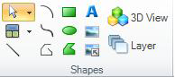
This topic describes the tools in the Shapes section of the 2D ribbon's Home tab. It includes the following topics:
On the ribbon's Home tab, in the Shapes section you can click the Select icon's ![]() drop-down list button to access a menu that displays with the following options:
drop-down list button to access a menu that displays with the following options:
Select All Dynamic Objects menu item – Click this option to select all object dynamics in the display. Note that, by default, objects at the top level in the Explorer are considered; grouped objects are not. To select all dynamics in objects in a particular group, click this option (top-level objects are selected), then click the group in the Explorer.
Select All Of Type: type menu item – Click this option to select all objects of a particular type. This menu item is available only when an object is selected; the selected object's type becomes the type that appears in this menu item. For example, if a rectangle shape is currently selected, the this menu item lets you select all of the rectangles in the display. If multiple objects are selected, the key object’s type appears in this menu item. (The object that was selected last is the key object; it is the object that is surrounded by solid blue handles.)
Select All Objects menu item – Click this option to select all objects in the display. In this case all objects are selected at once, so the key object becomes the most-recently updated object.
For other ways to select shapes and objects in a display, refer to the Selection topic.
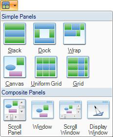
You can choose a set of panels to be added to a display by clicking the Panels icon in the Shapes section. For detailed information about panels, refer to the Panels topic.
The Panels Icon
To add a shape to the display:
Click the 2D Home ribbon to view the Shapes section.
Click the shape tool for the shape type you wish to create, then add the shape to the work surface in one of the following ways:
See also:
Adding a Glow, Shadow, Blur, or Opacity Effect
The Shift key is used to constrain the shapes you draw so that they either fall along a specific angle or are a perfect shape. When you use the Shift key when drawing a shape it performs the following actions:
Line tool. With the line tool, holding down the Shift key constrains the line you draw to any one of the 15° incremental directions, as follows: 0° , 15° , 30° , 45° , 60° , 75° , 90° , 105° , 120° , 135° , 150° , 165° , 180° , 195° , 210° , 225° , 240° , 255° , 270° , 285° , 300° , 315° , 330° , 345° , or 360° (0° ). As you move your mouse (with the button down) your line snaps to the line with the angle closest to one of these numbers.
Rectangle tool. Holding down the Shift key restricts the shape to a perfect square.
Ellipse tool. Holding down the Shift key restricts the shape to a perfect circle.
Label, Embedded Image, Referenced Image, and 3D Viewport tools. Holding down the Shift key restricts the shape you draw to a true square.
Spline, Polyline and Polygon tools. Holding down the Shift key constrains each line you draw to one of the 15° angles mentioned for the Line tool above.
Arc tool. Holding down the Shift key constrains the arc you draw to the ones that go from the center of the square bounding box to any one of the four vertexes of that square.
You can also use the Shift key when rotating shapes. For more information, refer to Rotating Objects in 2D.
See also:
Select, Move, Skew, Rotate a 2D Object
Dynamics in the GraphWorX64 Interface