![]()
![]()
Hyper Alarm Server was created to provide improvements over previous ICONICS alarm server technology. It was built to extend beyond the current limitations of ICONICS AlarmWorX64, listed below.
AlarmWorX64 Server Integration Limitations
DCOM-based - OPC AE 1.0 (legacy communication interface)
C++/ATL-based Code - Can’t be ported to other platforms
AlarmWorX64 Server Functional Limitations
Redundancy – Many limitations given by design, mainly because redundancy was added after initial release and original design didn’t count with it
Configuration
Concept of Configuration Trees and their Relations Comes from GENESIS v6 – System of network nodes, areas, alarms flat list, etc.
Alarm Templates should be Revised
Hardcoded Limit for 20 Related Values - Names of these values are also hardcoded
Complex Alarm Configuration – Many types of unrelated alarms in a single database entity
Runtime
Rate of Change/Rate Limit Doesn’t Work as Expected - Proper implementation would require a short data history
ICONICS Hyper Alarm Server was created to meet the following goals.
Integration
Native Integration with FrameWorX Infrastructure - Common ICONICS communication infrastructure
Developed as a Portable Set of Components - .NET standard
Possible Integration of Alarm Components in Other Products – Independent on Hyper Alarm Server configuration database
Functional
Flexible Design - To allow alarm customization
Reduced Configuration Complexity
Built-in Redundancy
Possibility to Access Historical and Other 3rd-party Data
Asynchronous Processing – long evaluation of a single source doesn’t block other sources
Alarm messages are generated by “alarm sources” hierarchically organized in a tree structure of “areas”. To configure a single alarm, the original alarm server needed to create a Configuration entity and then a configured alarm source underneath the Configuration object. Then, the alarm source had to be associated with area(s).
Alarm source configuration always included all possible configuration options and combination of alarm types. The related configuration form was very complex, thus its configuration wasn’t very intuitive. Due to hardcoded types of alarms, it wasn’t possible to create a multi-level alarm with more than two levels on each side of a “normal” condition (lo and hi conditions).
The original alarm server tried to reduce the configuration complexity by use of “alarm templates”. Alarm templates pre-set specific alarm source properties to reduce a need to configure them again and again for each alarm source.
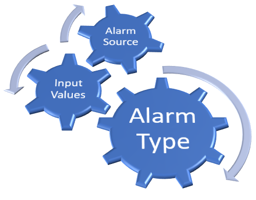
Hyper Alarm Server uses a different concept to overcome previous configuration and functional limitations. Instead of creating a complex alarm source configuration, which should cover all possible scenarios, and then using templates to reduce number of configured settings, the new alarm server defines an “alarm type” to define an alarm source behavior and structure. “Alarm source” is then associated with “alarm type” and userd configure type-specific properties only. In general, this concept allows users to design alarms based on their actual project needs.
In the new alarm server design, an alarm type is an essential part of alarm configuration. The alarm type defines alarm behavior by defining the following type elements:
Inputs - A set of values to be configured in the related alarm sources
Evaluation Logic Based on Expressions
Settings – suppressed states behavior, alarm delays
Conditions and Sub-conditions
Fields - Originally known as related values; a set of values send to a client with each alarm state transition
Values – Interconnection between fields and conditions
Triggers - When an alarm source should be evaluated
Input values specify all alarm source inputs – i.e. all values that can be configured within related alarm sources. As such, a part of their configuration is GUI-based properties (browsers, type of data, etc.). Input values can then be referenced within the whole alarm type definition as inputs into evaluation expressions, fields, and settings.
Every alarm type allows for specification of any number of alarm conditions. At minimum, two conditions must be configured – one “Normal condition” and an “Alarm condition”. Every condition is identified by an integer number in the range of [-1000, 1000], which gives us the possibility to specify up to 2000 alarm conditions. Normal condition is always identified by the zero code number – i.e. all non-zero code conditions are treated as alarm conditions.
Alarm evaluation logic is based on GENESIS64 expressions. The expression must return an integer number (or a value that can be converted to integer value), which represents a single alarm condition. All input values defined for this alarm type can be used as expression input variables. Moreover, each alarm condition can override the main evaluation expression – e.g., when a Hi alarm is generated, then another expression can be used to generate “return to normal condition”. To a certain extent, this can simplify expression coding.
The Fields are the set of values sent to a client application with each alarm transition. Fields can be either one of predefined fields (message, severity, etc.) or a custom field. Custom fields allow users to specify their field name and data type while, for predefined fields, users can specify a default value only (field name and data type is fixed).
This part interconnects alarm conditions with fields. Values are shown in tabular form and allow users to specify different values for each field based on active condition. A good example can be alarm severity for level alarms. A HiHi alarm condition may have severity of 1000, while a Hi alarm condition only 500.
Trigger events determine when specific alarm sources should be evaluated. Each alarm type allows for configuring one or more alarm triggers. The upper limit for a trigger count is not specified, but it should be kept on a reasonable level. Each trigger consumes some resources. Two basic trigger types are available: data change and time-based triggers. Data trigger input can be associated with an input value only – i.e. it doesn’t allow direct access to any other data source.
These represent all settings that are common for all conditions and fields. These settings cover on/off delay times and suppress state management (enable/disable shelve, out of service, suppressed by design and theirs values).
The initial version of Hyper Alarm Server supports the ISA 18.2 state machine in two modifications – with and without the Latch state. The Alarm Server internal concepts allow for adding more state machines in the future, if needed.
An Alarm Source must specify its alarm type and, based on the selected type, fill-in input values. The selected alarm type then defines alarm source behavior.
Alarm Source Concept
Similar to the original alarm server, all sources are organized in a tree structure of areas. Clients, like the AlarmWorX64 Viewer, then subscribe to an area, or to the root. Additional filters can also be specified. The Hyper Alarm Server is accessible as an out-of-process FrameWorX Server point manager. This is the only client interface directly embedded to Hyper Alarm Server.
Alarm data is available via alarm subscriptions or as real-time process points and methods located underneath each alarm source. This concept is the same as in the original alarm server implementation.
Like with Hyper Historian, Hyper Alarm source configuration can be done within AssetWorX on each Equipment Property. Such alarm sources are then accessible via the AssetWorX point manager interface, as well as through the Hyper Alarm Server point manager interface.
Standard two nodes redundancy to synchronize the alarm server state is supported. The active node processes alarms while the backup node synchronizes alarm source states with the active node. User actions, such as alarm acknowledgement, are always processed on the active node, while non-active ones get an update via the redundancy synchronization interface. Redundancy assumes that configuration databases for both nodes are identical. They should ideally connect to the same remote database with local caches. However, the code is tolerant to unsynchronized data in configuration databases. Both nodes identify alarm sources for synchronization by their browse location in the alarm address space. The redundancy exchange utilizes FrameWorX’s communication channel.
Redundancy information is available in MonitorWorX Viewer or as a set of process points and methods.
Client-side redundancy uses the standard redundancy model implemented in the FrameWorX Server.
The Hyper Alarm Server uses the AlarmWorX64 Server license, so it can be used with any product that includes AlarmWorX64 Server. Licensing is node-based, so the Hyper Alarm Server and AlarmWorX64 Server can both run on the same machine at the same time even with only one available AlarmWorX64 Server license. The Hyper Alarm Server consumes GENESIS64 tags for alarm inputs.
The Hyper Alarm Server is also available for IoTWorX edge devices.
See Also: