![]()
![]()
This Quick Start provides an introduction to the Hyper Alarm Server with examples and troubleshooting information.
The Hyper Alarm Server offers ISA 18.2-compliant and redundant alarming. The Hyper Alarm Server is built on new technology to provide better performance and more customization for the alarms generated.
The Hyper Alarm Server and the AlarmWorX64 Server both create alarms based on input tags, but there are a few differences in their behavior. Some of the most notable differences are below:
|
Feature |
AlarmWorX64 Server |
Hyper Alarm Server |
|
Alarms in multiple areas |
✓ |
|
|
Multiple configurations in one database |
✓ |
|
|
Templates |
✓ |
✓ (alarm types) |
|
Customizable alarm logic |
|
✓ |
|
Real-time inputs |
✓ |
✓ |
|
Historical data inputs |
|
✓ |
|
Runtime configuration changes via DA points |
✓ |
|
|
Max related values per alarm |
20 |
Unlimited |
|
Integrated with AssetWorX |
|
✓ |
|
ISA 18.2 compliance |
✓ |
✓ |
Currently, there is no method to convert an AlarmWorX64 Server configuration to a Hyper Alarm Server configuration. Users are encouraged to use the Hyper Alarm Server for new projects and continue using the AlarmWorX64 Server for existing projects unless there is a feature of the Hyper Alarm Server that warrants an upgrade.
ICONICS hopes that the Hyper Alarm Server will fit the needs of new projects better than the AlarmWorX64 Server. If this is not the case, please contact ICONICS technical support with the features of the AlarmWorX64 Server that cannot be replicated in the Hyper Alarm Server to help us close gaps in functionality.
When creating alarms in the Hyper Alarm Server, the first step is to create alarm types. These serve both as templates for your alarm tags and to define the logic behind an alarm. An alarm type defines the possible states or conditions, when the alarm should be enabled, specific types of related values, and more.
Alarm types are used in specific alarm tags, which are created in the Areas tree.
Hyper Alarm Server comes with several predefined alarm types that should fit the majority of use cases. The ability to define new alarm types or change the existing alarm types allows the user to greatly customize their alarm behavior in ways that was not possible in the AlarmWorX64 Server without patches or version updates.
The following sections describe the tabs of an alarm type.
General
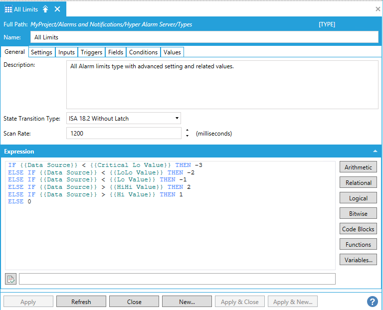
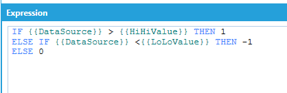
The General tab is used to create the expression for the processing of alarms. This is used with the Conditions tab to determine the logic behind the alarm states.
The expression on the General tab is one of the most important parts of an alarm type, which is why it has a prominent place on the front page, but it should be configured last. It uses fields from the Inputs tab and conditions defined on the Condition tab.
When an alarm tag of this type is evaluated, this expression is run. The expression should result in an integer. The integer is then matched to one of the conditions on the Conditions tab to determine the condition of this alarm tag.
Figure 1 - General Tab
Settings
The Settings tab is used to configure a number of optional settings for each alarm type. If a setting is not configured it will use a default value. The available setting and their default values are described in the table below.
|
Setting |
Description |
Default Value |
|
Enable User Out of Service |
Allows users to manually set Out of Service |
False |
|
Out of Service |
Allows automatic Out of Service to be triggered (Enable User out of Service must be disabled) |
Disabled |
|
Enable User Suppressed by Design |
Allows users to manually set User Suppressed by Design |
False |
|
Suppressed by Design |
Allows automatic Suppressed by Design to be triggered (Enable User Suppressed by Design must be disabled) |
Disabled |
|
Enable User Shelved |
Allows users to manually set Shelved |
False |
|
Shelved |
Allows automatic Shelved to be triggered (Enable User Shelved must be disabled) |
Disabled |
|
Alarm On-Delay |
Time alarm waits before switching to alarm state |
0 seconds (no delay) |
|
Alarm Off-Delay |
Time alarm waits before switching to the normal state |
0 seconds (no delay) |
Inputs
The Inputs tab defines the set of values needed to create a specific alarm using this type. When an alarm tag is created using the alarm type, the user will be presented with a form made up of the inputs defined on this tab.
Each input has a number of properties that are used to create the form, including the category, display name, input type, and default value.
Figure 2 – Input Parameters on Alarm Source Entry
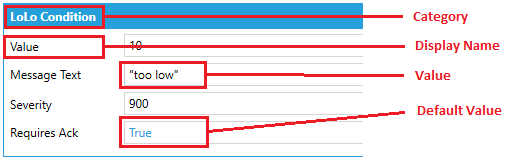
Some properties provide a list of preconfigured values. Select the tag button next to a property to see its available values. These values can be localized for the alarm tag form, which means if these values are used for the input section, they will change based on the language for GENESIS64. If a custom string is entered here, they will not be translated.
Triggers
The Triggers tab is used to determine when the alarm should be evaluated for possible condition changes. Triggers can be based on either time or data change. Alarm types can have multiple triggers.
Fields
The Fields tab is used to determine what fields from the alarm are sent to clients (such as the AlarmWorX64 Viewer). In addition to standard fields, such as Message and Severity, the user can create their own custom fields. These act as related values and can have customized names.
The default value for fields can use information defined on the Inputs tab.
Conditions
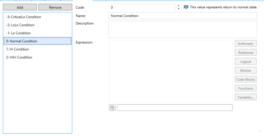
The Conditions tab is used to create the different conditions for alarms. The result of the expression on the General tab is matched to the code of one of these conditions to determine the condition or state of the alarm.
When creating the conditions, code 0 should always be used for the normal state.
Figure 3 - Conditions Tab
Values
The Values tab shows the conditions and the fields in a table to allow specific conditions to provide different field values in runtime.
For example, if the user wants to create an alarm type that has a severity of 500 when it is in the normal state but higher severity when it is in the Hi or HiHi state they can set the default severity to 500 on the Fields tab and set higher severities for Hi or HiHi on the Values tab.
Values that come from the defaults defined on the Fields tab are shown in blue. Edited values are showed in black.
Alarm tags are created under Hyper Alarm Server > Areas.
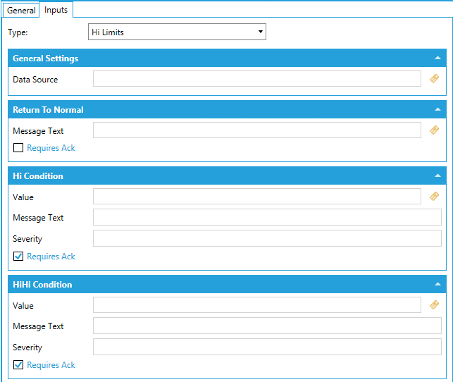
The General tab of each alarm tag has basic options for the display name and description. On the Inputs tab the user chooses a type out of the defined alarm types, then the rest of the Inputs tab is populated based on the defined inputs of that alarm type.
Figure 4 – Alarm Source Configuration
Use a Sample Alarm Type
Right click on an area or right click on Areas and choose Add Tag.
Give this alarm a name and click on the Inputs tab.
Select Digital in the Type dropdown list.
On the Input tab fill out the fields for the alarm. An example of the values is below. String parameters need to be surrounded with double quotes.
|
Section |
Property |
Value |
|
General Settings |
Data Source |
@sim64:Bool.Static("Static1").Value |
|
General Settings |
Default Display |
C:\Program Files\ICONICS\GENESIS64\WebSites\PubDisplay\DataExplorer.gdfx |
|
General Settings |
Base Text |
“Alarm 1 is “ |
|
General Settings |
Help Instructions |
“Alarm Tag 1 is in the alarm state, see related values for other related properties on the alarm” |
|
Alarm State |
Value |
1 |
|
Alarm State |
Message Text |
“in alarm” |
|
Alarm State |
Severity |
800 |
|
Alarm State |
Requires Ack |
Checked |
|
Return to Normal |
Message Text |
“is normal” |
|
Return to Normal |
Requires Ack |
Unchecked |
|
Related Values |
1 |
@sim64:Float.Static("Static1").Value |
|
Related Values |
2 |
@sim64:Double.Static("Static1").Value |
Click Apply after entering in the data for the alarm. When the source tag is greater than 1, the alarm will show as active in the AlarmWorX64 Viewer.
Create and Use Your Own Alarm Type
This example creates an alarm type that has both a HiHi condition and a LoLo condition for the alarm.
Go to the Hyper Alarm Server and right click on Types to add a Type.
Go to the conditions tab and add three conditions with three unique values for code and give each condition a unique name. These will be used to determine if the alarm should be in LoLo, Normal or HiHi state. For this example, LoLo is -1, Normal is 0, and HiHi is 1.
Now go to the Inputs tab and create the following inputs. Some properties have dollar signs around them because these are the predetermined names of the fields. These can be used to allow localization of the fields. The user can put in their own strings, but they will not be translated if the language of GENESIS64 is changed.
|
Category |
Name |
DisplayName |
Input Type |
|
$GeneralSettings$ |
DataSource |
$DataSource$ |
Dynamic |
|
$LoLoConditions$ |
LoLoValue |
$Value$ |
Dynamic |
|
$LoLoConditions$ |
LoLoText |
$MessageText$ |
Dynamic |
|
$Normal$ |
NormalText |
$MessageText$ |
Dynamic |
|
$HiHiConditions$ |
HiHiValue |
$Value$ |
Dynamic |
|
$HiHiConditions$ |
HiHiText |
$MessageText$ |
Dynamic |
Go to the Fields tab and add in one field using the Add button. On this field select Message from the Field Type list. Now repeat this for Severity and Requires Ack. After this, there should be three items in the list: Message, Severity, and RequiresAck.
Now go back to the General tab and create the expression below. In the example below, 1 is the HiHi state, -1 is the LoLo state, and 0 is the Normal state.
Figure 5 - Expression for HiHi and LoLo Alarm
After doing this, click Apply.
Go to the Triggers tab and add in a data trigger for Data Change and set the input to DataSource.
On the Values tab set the table up using the table below.
|
Condition Name |
Severity |
Message |
RequiresAck |
|
LoLo |
700 |
{{LoLoText}} |
1 |
|
Normal |
700 |
{{NormalText}} |
0 |
|
HiHi |
700 |
{{HiHiText}} |
1 |
Give the Alarm Type a name and then click on Apply to save changes.
After making this Alarm Type, go to the Areas section and add an alarm tag using this new alarm type.
Add in the properties for this new alarm type. The string parameters (such as message) need to be surrounded by double quotes. An example of a configured alarm is below.
|
Section |
Property |
Value |
|
General Settings |
Data Source |
@sim64:Float.Static("Static1").Value |
|
LoLo Condition |
Value |
20 |
|
LoLo Condition |
Message Text |
“Tag is LoLo” |
|
Return To Normal |
Message Text |
“Tag is Normal” |
|
HiHi Condition |
Value |
50 |
|
HiHi Condition |
Message Text |
“Tag is HiHi” |
Click Apply after entering in the data for the alarm. When the tag is either higher than the HiHi limit or lower than the LoLo limit, the alarm should show in the AlarmWorX64 Viewer.
Create Alarms in AssetWorX
The Hyper Alarm Server can also be integrated into AssetWorX to allow alarms to use the AssetWorX properties. The alarms will use the AssetWorX path for the name and the point in the AssetWorX Real-Time Data property as the input. This example uses the sample configuration for the Hyper Alarm Server and AssetWorX. Both of these configurations need to be in the same database to use this feature.
Go to AssetWorX and find the AssetWorX Property the alarm will be created on. For this example, the property used is Equipment → Company → Foxboro Bakery → North → Baking line → Ingredients mixing tank → Ingredient charger → Heating control → CurrentTemperature
After opening the AssetWorX property, go to the Alarm tab and check the box labeled “Hyper Alarm Server alarm”.
Select the Type from the dropdown list. For this example, select Hi Limits.
Fill in the information for the alarm and click Apply.
|
Section |
Property |
Value |
|
Return to Normal |
Message Text |
"Alarm is Normal" |
|
Hi Condition |
Value |
50 |
|
Hi Condition |
Message Text |
"Alarm is Hi" |
|
Hi Condition |
Severity |
800 |
|
Hi Condition |
Requires Ack |
Checked |
|
HiHi Condition |
Value |
80 |
|
HiHi Condition |
Message Text |
"Alarm is HiHi" |
|
HiHi Condition |
Severity |
800 |
|
HiHi Condition |
Requires Ack |
Unchecked |
After clicking Apply the alarm will show in the AlarmWorX64 Viewer with the AssetWorX path as the tag name.
The Hyper Alarm Server can be subscribed to via the AlarmWorX64 Viewer and through other GENESIS64 clients as either data points or Alarm and Event Subscriptions.
The address space for the Hyper Alarm Server is separated out into different sections. The first section is AssetWorX integration, then the Redundancy information shown, and lastly the area tree where the alarms are created.
Figure 6 - Sections of Data Browser
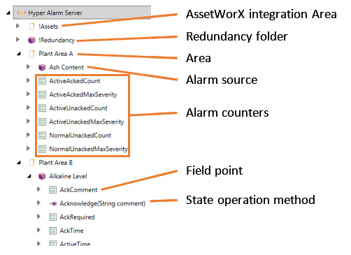
When subscribing to the entire Hyper Alarm Server via the AlarmWorX64 Viewer, the path would be:
alms:
Hyper Alarm Server has redundancy built into the product using FrameWorX redundancy as a base. The behavior for Hyper Alarm Server redundancy is that the active server processes alarms and acknowledgements for the clients. For the standby server, it synchronizes the alarm states with the active server. Both servers should have the same configuration database with the same settings in them.
The configuration settings for redundancy are in the Product Configuration → System Settings section of the Hyper Alarm Server tree.
The settings for redundancy are the Primary Computer Name and the Secondary Computer Name. These are to set the two servers being set for redundancy. The Primary Host and Secondary Host are backup hostnames or IP addresses to connect to the server machines. This is used in case the original host name is inaccessible.
The Hyper Alarm Server has built in features to assist in troubleshooting issues.
Counters
Counters are used to expose information about the number of alarms active or max severity to clients or Windows Performance Monitors to see the overall performance of the Hyper Alarm Server.
In the default configuration, some counters are already created in the system and can be exposed as process points to clients. Some examples are the count of active and acknowledged alarms, the maximum severity of active and acknowledged alarms, etc.
More counters can be created by going to Product Configuration → Counters in the Hyper Alarm Server tree. These would be created by adding a new counter and creating a new expression that uses properties of the alarms.
Point Tracing
Point tracing is built into the Hyper Alarm Server to track the values of the inputs using TraceWorX. This is used to troubleshoot the expressions made for the alarm types and to see the process the expression followed when the alarm triggered.
To enable Point Tracing go to the Product Configuration → System Settings section of the Hyper Alarm Server tree and find the section called Point Tracing. In this section, check the Enabled box and this will enable point tracing.
There are different fields that can be enabled for TraceWorX and they are used for troubleshooting different sections of the alarms. A&E Point Names is used to choose which alarms to trace. The A&E Field Names and A&E Type Setting Names are the properties of those alarms to be traced.
For the A&E Field Names, the default Field Types need to start with the @ symbol (@Message, @Severity, @RequiresAck). Custom field names are just the name of the field. For the A&E Type Setting Names, these match the list shown on the Settings tab of the Alarm Type. To put these into TraceWorX, use the name without spaces (EnableUserOutOfService, OutOfService, EnableUserSuppressedByDesign, SuppressedByDesign, EnableUserShelved, Shelved, AlarmOnDelay, AlarmOffDelay).
The input and output point names are used to track the values of the inputs to the Hyper Alarm Server (OPC points) and the outputs from the Hyper Alarm Server to other GENESIS64 clients. For multiple tags, separate with semicolons.
|
Point Tracing Setting |
Description |
Example |
|
A&E Point Names |
List of alarm tags in Hyper Alarm Server to trace, separated by semicolons. |
.AlarmTag;/Area1.Source1 |
|
A&E Field Names |
List of Field names from the alarms enabled in the A&E Point Names |
@Message;DefaultDisplay |
|
A&E Type Setting Names |
List of Type Setting from the alarms enabled in the A&E Point Names |
EnableUserOutOfService; OutOfService |
|
Input Point Names |
List of points being requested by the Hyper Alarm Server |
PathtoOPCTag1; |
|
Output Point Names |
List of Hyper Alarm Server points being requested by GENESIS64 clients. |
alms:/Plant Area A=ActiveAckedCount; alms:/Plant Area A.Ash Content@ActorId |
Finally, open TraceWorX by navigating to Tools > TraceWorX in the Workbench. Find the Hyper Alarm Server Point Manager Service in the Modules list and set the Trace Level to Severe Error (900). Click Save Changes. This will enable tracing at the 900 level, and we will have the Point Tracing messages in the log as well. There is no need to restart the Hyper Alarm Server service – it supports online changes.
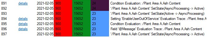
After enabling these settings, messages like in Figure 7 will appear in the TraceWorX log.
Figure 7 - Example TraceWorX Messages
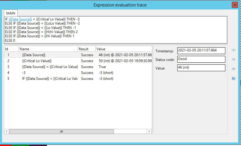
Clicking on one of the details links will show the expression evaluation trace which breaks down the expression for the alarm itself. This is useful for seeing the result of the expressions for the alarms.
Figure 8 - Expression Evaluation Trace
See Also: