![]()
![]()
The system configuration when using Mitsubishi Electric FA allows for configuring a MELSEC within ICONICS Workbench. See MELSEC System Configuration for more info.
Note: MELSEC can only be edited when disabled. When the device is activated, settings cannot be changed until the device is disabled. See Activate and Disable.
To Add MELSEC
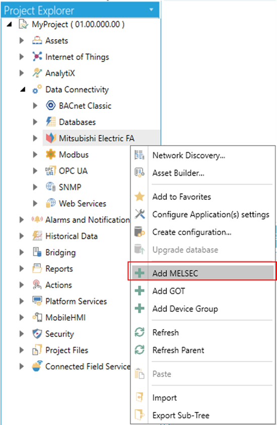
In the Workbench, expand your project in the Project Explorer, and then expand the Data Connectivity node. Right-click the Mitsubishi Electric FA node and click on Add MELSEC as shown below.
Add MELSEC via the Project Explorer in the Workbench
-OR-
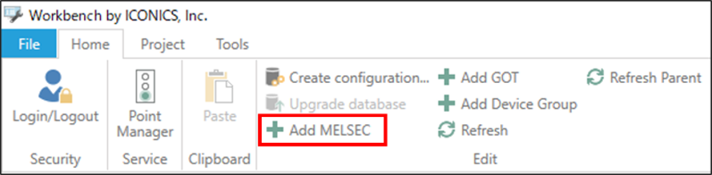
Select the Mitsubishi Electric FA node in the Project Explorer in the Workbench and then click on the Add MELSEC button shown below in the Edit section of the Home ribbon.
Add MELSEC button
This opens the MELSEC Properties shown below in the central section of the Workbench. Enter a name for the MELSEC device in the Name text entry field.
MELSEC Properties (Device Settings)
.png)
Common Settings
(Click to test the communication) - Click this link to connect to the actual device for test.
Description - Enter a description for the MELSEC device in the text entry field.
CPU Series - Use the pulldown menu to select the CPU series. Selectable CPU Series are as follows: RCPU, RSafety, LHCPU, FX5CPU, QCPU, LCPU, FXCPU, QSCPU. [Note: See MELSEC System Configuration for additional compatible system-related details.]
CPU Type - Use the pulldown to select a CPU type which is based on the selected CPU Series above. [Note: See MELSEC System Configuration for additional compatible system-related details.]
If RCPU CPU Series Selected: R00, R01, R02, R04, R08, R16, R32, R120, R04EN, R08EN, R16EN, R32EN, R120EN, R08P, R16P, R32P, R120P, R08PSF, R16PSF, R32PSF, R120PSF
If RSafety CPU Series Selected: R08SF, R16SF, R32SF, R120SF
If LHCPU CPU Series Selected: L04H, L08H, L16H
If FX5CPU CPU Series Selected: FX5U/FX5UC, FX5UJ
If QCPU CPU Series Selected: Q00UJ, Q00U, Q01U, Q02U, Q03UD, Q03UDE, Q03UDV, Q04UDH, Q04UDEH, Q04UDV, Q04UDPV, Q06UDH, Q06UDEH, Q06UDV, Q06UDPV, Q10UDH, Q10UDEH, Q12PRH, Q13UDH, Q13UDEH, Q13UDV, Q13UDPV, Q20UDH, Q20UDEH, Q25PRH, Q26UDH, Q26UDEH, Q26UDV, Q26UDPV, Q50UDEH, Q100UDEH
If LCPU CPU Series Selected: L02S/L02S-P, L02/L02-P, L06/L06-P. L26/L26-P, L26-BT/L26-PBT
If FXCPU CPU Series Selected: FX3S, FX3G/FX3GC, FX3U/FX3UC/FX3UC-32MT-LT-2
If QSCPU CPU Series Selected: QS001
· Use Simulator - Click the checkbox to use simulators and enable Simulator Settings.
[Note: QCPU, LCPU, FXCPU, QSCPU do not support the use of simulator and this option is grayed out when one of these PLC series is selected]
· Timeout - Enter a timeout in seconds in the text entry field (or use the “up/down” arrow buttons) to cease communication attempts upon error.
· Retry - Enter a number of communication retries in the text entry field (or use the “up/down” arrow buttons).
PC I/F Settings
PC I/F - Use the pulldown menu to select a PC I/F (interface function) from USB, Serial, Ethernet Board, or CC IE Control Board. [Note: See System Configuration for additional compatible system-related details.]
IP Address - Enter the IP address for the PC I/F (interface function) in the text entry field.
COM Port Number - Enter a COM port number for the PC I/F (interface function) in the text entry field (or use the "up/down" arrow buttons).
Source Network Number - Enter a source network number in the text entry field (or use the "up/down" arrow buttons).
Source Station Number - Enter a source station number in the text entry field (or use the "up/down" arrow buttons).
Board Number - Use the pulldown menu to select from the 1st Module to the 4th Module for CC-Link IE Control Board.
MELSEC I/O Settings
MELSEC I/F - Use the pulldown menu to select a MELSEC I/F (interface function), which is based on the combination of CPU Series, CPU Type, and PC I/F settings above. Note that some of the settings in the remainder of this section may be active or inactive based on the selection of the specific CPU Series, CPU Type, and PC I/F combinations. [Note: See MELSEC System Configuration for additional compatible system-related details.]
Protocol Type - For Ethernet Board interfaces that require '(Specify IP Address)', use the pulldown menu to select from either TCP or UDP.
Network Number - For CC-Link IE Control Board interfaces, enter a network number in the text entry field (or use the up/down arrow buttons).
Station Number - For Ethernet Board interfaces [specifically RJ71EN71 (Specify IP Address / Direct), QJ71E71 (Specify IP Address), LJ71E71 (Specify IP Address) or RJ71GN11-T2 (Specify IP Address)specifically RJ71EN71 (Direct), or RJ71EN71 (Specify IP Address)], or CC-Link IE Control Board interfaces or Serial interfaces, enter a station number in the text entry field (or use the up/down arrow buttons).
IP Address - For Ethernet Board interfaces that require '(Specify IP Address)', enter an IP address for the MELSEC I/F in the text entry field.
Baudrate - For Serial interfaces, use the pulldown menu to select a baudrate from 9600, 19200, 38400, 57600, or 115200.
Control - For Serial interfaces, use the pulldown menu to select from DTR Control, RTS Control, DTR and RTS Control, or DTR or RTS Control.
Redundant Mode - When active, check this box if you want to access Redundant CPU. You can use the nearby pulldown menu to select from Not Specified or Control System.
Simulator Settings
System Number - Enter a number between 1 and 4 in the text entry field (or use the "up/down" arrow buttons) for the number of simulators to connect
PLC Number - Use the pulldown menu to select the PLC number between 1 and 4 to connect.
Other Settings
Merge Gap - Enter a value larger than the number of registers between tags when reading inconsecutive registers in a batch in one communication between Mitsubishi Electric FA and a MELSEC device. This setting is for adjustment and is usually left at its default value of 64.
Please refer to Merge Gap Details for details.
3. Click Apply to save your changes to the configuration and Close to return to the Workbench.
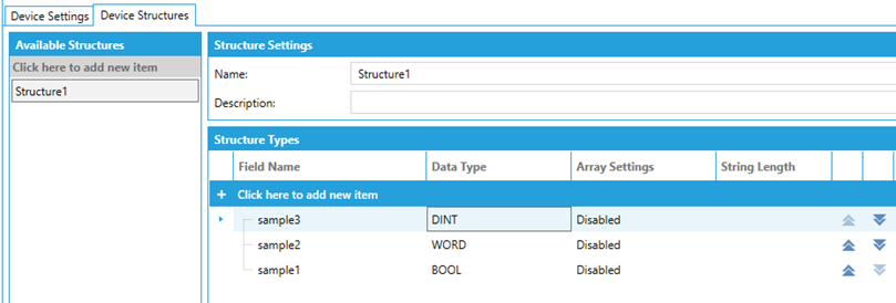
MELSEC Properties (Device Structures)
Available Structures
· Click here to add new item - Click to add a new device structure.
Note: If a device structure is referred by one or more tags, the structure is displayed with “(In Use)” and cannot be edited or deleted.
Structure Settings
· Name - Enter a name of the device structure in the text entry field.
· Description - Enter a description for device structure in the text entry field.
Structure Types
· Field Name - Enter a name for the structure member in the text entry field.
· Data Type *3 - Use the pulldown menu to select the tag's data type.
Options include:
BOOL *1, WORD, DWORD, INT, UINT, DINT, UDINT, LINT, ULINT, REAL, LREAL, STRING, WSTRING, STRUCTURE (*2)
*1 The BOOL can be used by specifying the bit position (e.g., EG0.1)
*2 The name of a device structure is displayed in the parentheses.
*3 All available the data types support the array type.
· Array Settings - Click the "Edit setting" icon to display the Array Configuration window. If the tag is an array type, the cell displays the shape of it (e.g., (0..2) for a single-dimensional array with 3 elements). If the tag is not an array type, the cell displays “Disabled”.
Please refer to Array Configuration Details for details.
· String Length - If the tag is a STRING or WSTRING type, the sell displays the length of the string (default: 32). The length of the string can be changed between 1 and 255. If the
tag is not a string type, the cell is blank.
· Move element up - Move the selected element one up. This cannot be used if the element is already on the top of the list.
· Move element down - Move the selected element one down. This cannot be used if the element is already at the bottom of the list.
To Add a Device Structure
1. Click the Device Structures tab to show the window for structure settings.
2. Click “Click here to add new item” to add a new device structure.
3. Provide a valid name to the added device structure
4. Click Apply to save the change.
To Add Members to a Device Structure
1. Select a device structure to add a new member.
2. Provide a valid name and select a data type for the member.
3. Click an Edit setting… icon that appears by clicking the Array Settings cell to enable an array if needed.
(Please refer Add Tag Group for the details of array settings)
4. Click Apply to save the change.
Note: If a structure is In Use by one or more tags, it cannot be edited and deleted.
See Also: