![]()
![]()
To use a state assignment with a Data Entry label in a 3D view:
Add an annotation to the 3D viewport.
Inside the annotation, create:
a Data Entry label, by putting the cursor in the annotation then clicking
and a Process Point, by putting the cursor in the annotation then clicking .
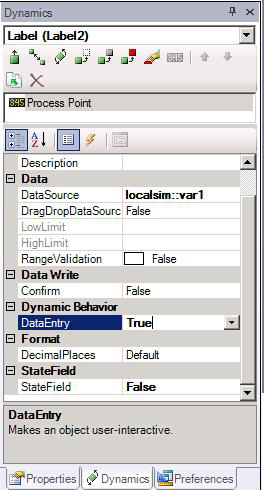
Set each of these objects' DataSource properties to localsim::var1; which is a declared variable. Because the Data Entry label is editable, its DataEntry property is set to True. Because the Process Point is not editable, its DataEntry property is set to False. Leave both objects’ DataEntry properties unchanged. (Note that, in the Dynamics tab, both a Data Entry label and a Process Point are called a "Process Point".)
For the Data Entry label: Create a collection of states. To do this, select the Data Entry label, then set its StateField property to True
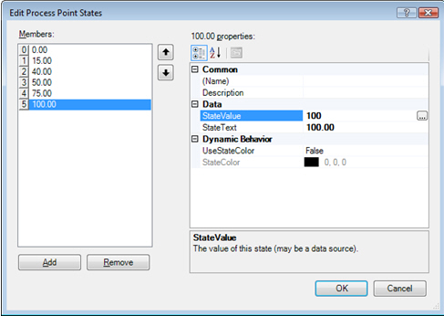
Click the ellipsis button ![]() in the States property. This opens the Edit Process Point States dialog box, if you are working in Standard mode. Define the states 0, 15, 40, 50, 75, and 100.
in the States property. This opens the Edit Process Point States dialog box, if you are working in Standard mode. Define the states 0, 15, 40, 50, 75, and 100.
Click the Add button to add the first state; a line is added to the Members box on the left.
Instead of values, we could have set the StateValue property to an OPC tag, an alias, or another variable value. The StateText is the label given to the state; you can use language alias or just type the text into the property field. You can also set the dynamic’s behavior so that the text changes color if the state is enabled.
|
|
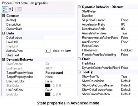
Note: If you are working in Advanced mode, additional state properties display. In Advanced mode, instead of entering the state value into the StateValue field, enter it into the LowLimit property. In Advanced mode, you can enter an acceptable range for the state by entering values for the LowLimit and HighLimit properties. |
For the Process Point: Select the process point in the annotation, and go to the process point’s Dynamics tab. Set its StateField to True, then click the States property’s ellipsis button ![]() . Enter the following values for the states' StateValue and StateText values and text respectively:
. Enter the following values for the states' StateValue and StateText values and text respectively:
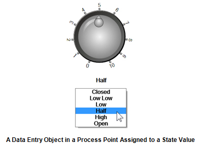
0 and Closed
15 and Low Low
40 and Low
50 and Half
75 and High
100 and Open
Drag a circular knob from the Symbols Library into the annotation. (Note that you can add a 2D knob to the annotation.) Select the knob’s indicator, and set the indicator’s DataSource to localsim::var1, the indicator’s LowLimit to 0 and its HighLimit to 100.
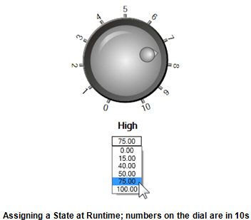
Click the Runtime button (at the top-right of the GraphWorX64 workbench) to go into runtime to see the annotation with its Data Entry label and Process Point. The text displayed above the list is the Process Point. (Numbers on the dial are in 10s; that is, 1 on the dial represents the value 10.)
As a runtime user makes selections from the Data Entry label, the text for the selected value displays in the Process Point and the knob’s indicator rotates to the corresponding position on the dial. Click the Configuration button at the top-right of the GraphWorX64 workbench to return to configuration mode.
To see the similarity between the Data Entry label and the Process Point, try changing the Process Point dynamic’s DataEntry property to True. This simple change lets runtime users set the value using the Process Point; the StateText text strings display instead of the StateField and States values.
Examples: