![]()
![]()
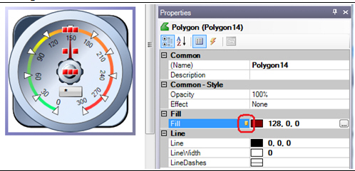
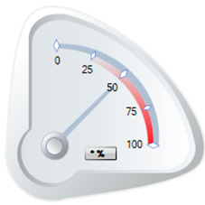
A typical example of a Smart Symbol is the gauge. When such a symbol is pasted into a GraphWorX64 display, it is often necessary to change the data source that drives the rotation animation bound to the needle. One could also change the color of the needle or the ranges. These changes in a normal object group require you to drill into the group using the Edit Group function or ungroup the symbol to modify the properties one by one.
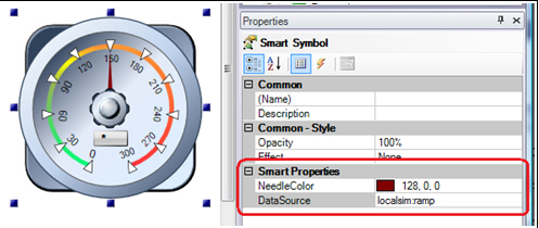
If such a group is converted into the Smart Symbol, properties like the data source, needle color, and ranges can be exposed as Smart Properties and configured in the Properties tab.
The remainder of this topic describes Binding the range of values and Complex data binding examples, which provide information for configuring Smart Properties. For more information about Adding and Editing Smart Symbols, see Smart Symbol Basics.
Smart Properties allow you to easily expose and edit properties of inner objects, but they also add an additional logic. For example, a gauge typically has a scale with several labels (or numbers or settings) on it, but you really only need to configure the low and high range of the scale. The labels between low and high limits can be calculated automatically.
Example. The following example shows you how to bind the low and high ranges as smart properties and how to dynamically calculate the rest of the labels on the scale.
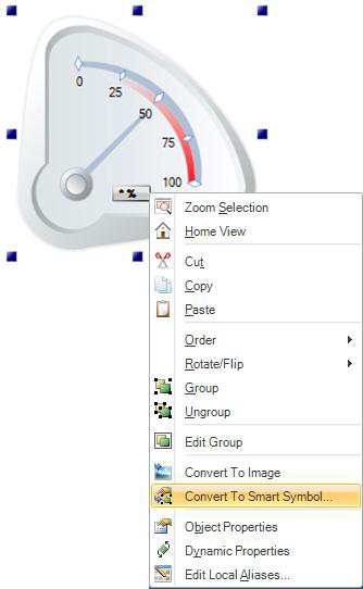
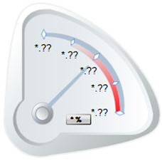
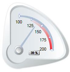
Insert the Circular Gauge Symbol (shown below) from the Symbol Library into your GraphWorX display.
If it is not already a smart symbol, convert it to a Smart Symbol by right-clicking on it and selecting Convert To Smart Symbol.
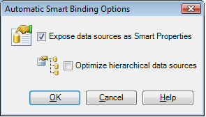
Select Expose Data Sources as Smart Values in the Automatic Smart Binding Options dialog box and click OK.
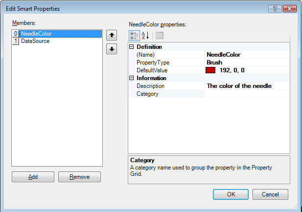
In the Edit Smart Properties dialog box, change the name to DataSource and click OK.
In the smart symbol, replace the scale labels 0, 25, 50, 75, 100 with process points. To do this, double-click until the group inside the symbol is selected, then insert five new process points and remove the (now obsolete) labels. Select all five process points and set the Decimal property in the Dynamics pane to 0 to hide decimal digits. Click here to see the scale labelled with process points.
Assign the data sources of the low range process point to a constant 0 and of the high range to a constant 100.
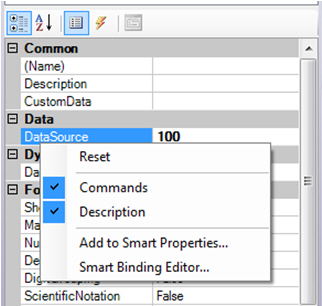
Right-click on the DataSource of the low range and high range process points and select the Add to Smart Properties item.
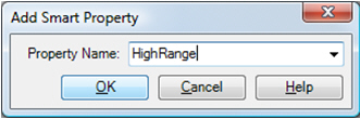
In the Add Smart Property dialog enter LowRange as the name of the Low Range property and HighRange as the name of the High Range property
Select the other three process points on the scale one by one, right-click on their data source field and select Smart Binding Editor item. Use the following expressions in the Binding Logic field:
for a 25% process point: {{LowRange}} + ( 1/4 ) * ( {{HighRange}} - {{LowRange}} )
for a 50% process point: {{LowRange}} + ( 2/4 ) * ( {{HighRange}} - {{LowRange}} )
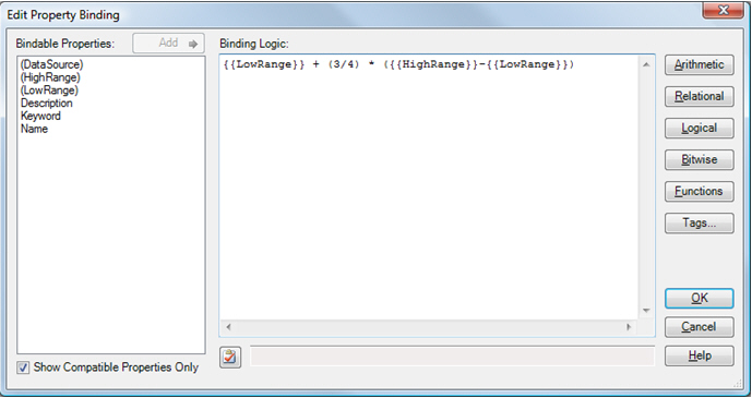
for a 75% process point: {{LowRange}} + ( 3/4 ) * ( {{HighRange}} - {{LowRange}} )
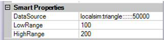
Select the whole symbol (press Esc or double-click outside the symbol until you select the whole gauge). Open the Properties tab and enter different ranges, for example from 100 to 200.
Go to Runtime mode the check the results. Note the low range equals to 100, high range equals to 200 and the labels between low and high range are automatically recalculated to reflect new ranges. Click here to see the gauge example.
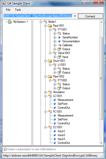
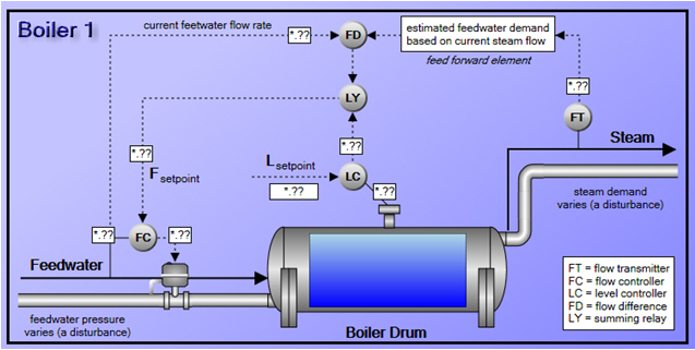
The idea behind automatic complex data binding for Smart Symbols is to be able to bind a symbol to a single complex data object via a single Smart Property and automatically have numerous contained animations hooked up to attributes of the complex data object. This is particularly relevant to OPC UA in which complex objects and data types may be provided via an OPC UA Server. For example, the structure of a “Boiler” object exposed from an OPC UA Server sample client.
Within the Boiler symbol, the following data sources are used to connect to an instance of a Boiler called “Boiler1”.
http://localhost:5000/UA/SampleServer\Boiler1/[http://opcfoundation.org/UA/Sample/]FCX001.SetPoint
http://localhost:5000/UA/SampleServer\Boiler1/[http://opcfoundation.org/UA/Sample/]FCX001.ControlOut
http://localhost:5000/UA/SampleServer\Boiler1/[http://opcfoundation.org/UA/Sample/]LCX001.SetPoint
http://localhost:5000/UA/SampleServer\Boiler1/[http://opcfoundation.org/UA/Sample/]LCX001.Measurement
http://localhost:5000/UA/SampleServer\Boiler1/[http://opcfoundation.org/UA/Sample/]LCX001.ControlOut
http://localhost:5000/UA/SampleServer\Boiler1/[http://opcfoundation.org/UA/Sample/]PipeX001/FTX001.Output
http://localhost:5000/UA/SampleServer\Boiler1/[http://opcfoundation.org/UA/Sample/]PipeX002/FTX002.Output
http://localhost:5000/UA/SampleServer\Boiler1/[http://opcfoundation.org/UA/Sample/]DrumX001/LIX001.Output
Analysis of these data sources indicates that there is a hierarchical structure to the segments of the tag and a common root:
http://localhost:5000/UA/SampleServer\Boiler1
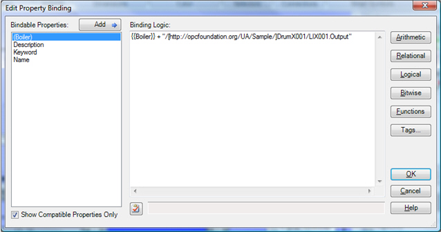
In this case, a single Smart Property can be created for the common root (Boiler), and the descendant properties can be bound to that Smart Property as a combination of the Smart Property value and the remaining unique segments of the tag. Click here to see an example of the Edit Property Binding dialog box.
After binding all of the data source properties to Smart Properties in this manner, all that is required to change the “instance” of the boiler symbol from Boiler1 to Boiler2 is to change the value of the Smart Property from:
http://localhost:5000/UA/SampleServer\Boiler1 to http://localhost:5000/UA/SampleServer\Boiler2.
The option to perform automatic complex data binding is provided when converting a group to a Smart Symbol and appears as the Optimize hierarchical data sources check box option is selected all descendant objects of the group are examined for existing data source connections. All found data sources are analyzed to determine common hierarchical roots. Then a new Smart Property is added for each unique hierarchical root, and the descendant data source properties are automatically bound to that Smart Property by combining the Smart Property value (the common hierarchical root) with the remaining unique portion of the data source (as described above).
See also:
Dynamics in the GraphWorX64 Interface