GraphWorX64 contains a powerful feature that detects the collision of two or more objects in a 3D view. The detected collision can trigger a variety of actions:
These actions can be triggered either when the collision occurred (On collision start), and/or when the collision has finished (On collision end).
This topic covers the basic concepts of collision detection of two objects in a 3D view. It is a brief introduction to collision detection in GraphWorX64 that shows you how to set up your display to trigger a GenEvent. If at any point in this example you need additional information, refer to the topics about 3D in GraphWorX64, and the other available topics about collision detection. Note that in addition to this example, you can also combine the collision with triggering a script to pop up a message about the collision. For scripting capabilities, refer to the scripting topics, such as the Scripting - Quick Start topic.
GraphWorX64 does not need any special configuration in order to detect a collision. You create the objects in the 3D view and select the objects you want to be enabled for collision detection. As such, you can finish your display and then decide which objects to be used for detecting collisions. Or you can do collision detection whenever you like while creating your display.
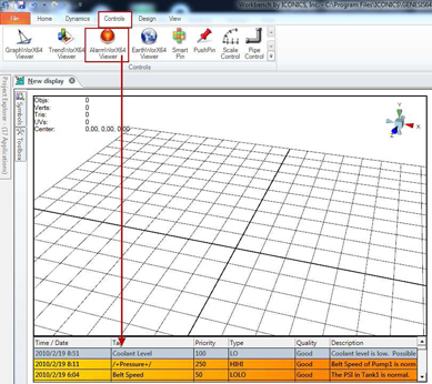
In this example, you will use two simple primitive objects: a sphere (a ball) and a cube (a wall). When these two collide, both will change colors and generate a GenEvent, which will be listed in the AlarmWorX64 Viewer.
Figure 1 - Display with a 3D View and an AlarmworX64 Viewer
Figure 2 - Create a Wall out of a Cube
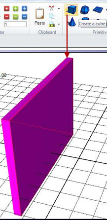
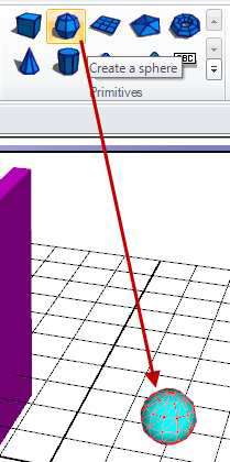
Figure 3 - Create a Sphere
Now you are going to let the sphere hit the wall using a simulated sine OPC Tag.
Figure 4 - Location Dynamic
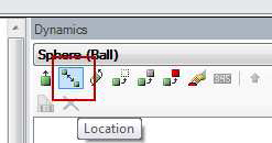
Figure 5 - Select a Simulated OPC Tag
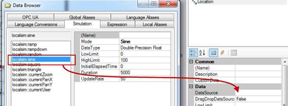
Figure 6 - Change the Path3D
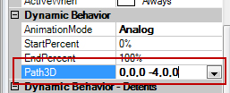
NOTE: Depending on your regional settings, you might find the coordinates separated by semi colon ( ; ). When you change values in this field, the coordinates must be separated by commas ( , ). If you need fractions, use point ( . ) as a decimal separator.
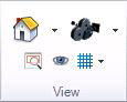
Figure 7 - View tools to quickly check our settings
If you did the runtime test, you will need to double-click inside the 3D view to continue editing.
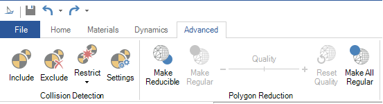
Go to the Collision Detection section on the Workbench ribbon's Advanced tab. You can use these tools to include, exclude, or restrict objects for the collision detection. For more information, refer to the Collision Detection Section of the 3D Dynamics Ribbon topic.
Figure 8 - The Collision Detection tools
You can select each object and include it, or select several and then click Include.
Later you will take a closer look at the “Settings” tool.
Figure 9 - Collision Detection Settings
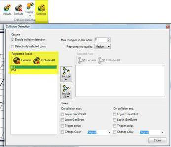
Figure 10 - Include Bodies to be Pairs
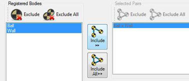
Figure 11 - Define the Rules
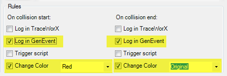
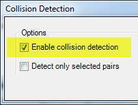
Figure 12 - Enable collision detection & close
In order to see the events posted by the collision detection, you need to configure the AlarmWorX64 Viewer.
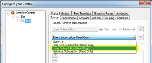
Figure 13 - Access the control configuration
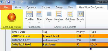
Figure 14 - Selecting the Event Subscription
Now is a perfect time to save your work. Next go into runtime and see what happens. You should see the ball move and collide with the wall. As soon as they collide, both objects turn red. And when the collision ends, they return to their original colors.
Figure 15 - Before Colliding
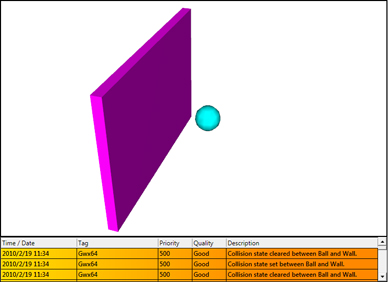
Figure 16 - Colliding
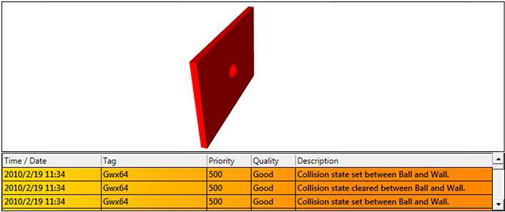
See in the AlarmWorX64 viewer the messages “Collision state set between Ball and Wall” and “Collision state cleared between Ball and Wall” alternate accordingly.
You can set up other scenarios for collisions, too. For example, you can add a new sphere and animate it to collide with the wall, but do not do anything when the balls collide with each other.
Try different settings in the Collision detection settings to become familiar with what it can do.
Figure 17 - Settings for More Pairs
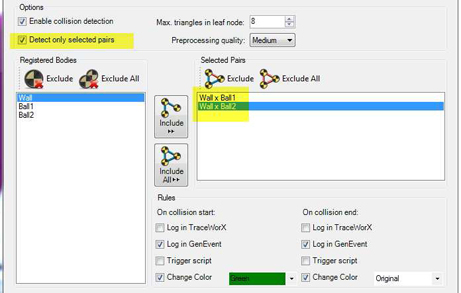
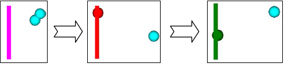
Figure 18 - Balls Colliding from Top View
See also:
Collision Detection TraceWorX Trace Log