The ICONICS Modbus OPC Server is an OPC-compliant OPC Data Access (DA) and Alarm & Events (A & E) Server that serves data to OPC clients.
The ICONICS Modbus OPC Server is based on the popular Modbus protocol and can be connected to real world Modbus compatible I/O hardware.
Advanced OPC data quality and data conversion to client's request.
Modbus OPC Server utilizes advanced threading capability of the Modbus Server.
Supports multiple multi-drop I/O devices.
Supports multiple groups for easy configuration and manageability.
Supports all popular PLC and RTU data types.
Internal simulated for configuration and testing.
OPC client for rapid testing of your OPC data connections.
Tag multiplier allows you to create hundreds of tags in seconds.
User interface for viewing tags, groups, and real-time signals.
Supports OPC Data Access (DA) and Alarm and Events (AE) specifications.
Flexible engineering units and signal ranges.
TraceWorX32 diagnostics support (logging data into XML file)
Sample OPC Client
This document will guide you through the steps of configuring your Modbus server and explains the advanced features available including advanced server settings.
Start the Modbus Configurator by going to Start > ICONICS Modbus OPC Server > Modbus OPC Configurator.
Modbus Configurator
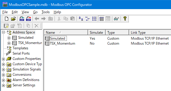
NOTE: You will notice a default configuration, which can be used to add a new Device or create new configuration file to start. If you choose to create a new configuration, make sure it is made active.
OPC Modbus Server v3.8 lets users add Modbus Serial or Modbus Ethernet Devices in the same configuration. Follow the steps below to define your device.
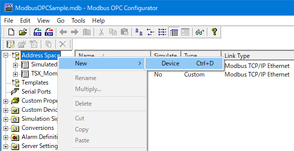
Right-click on Address Space and select New > Device.
New Device
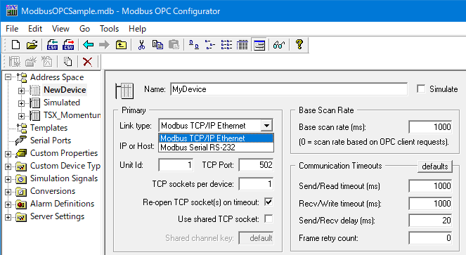
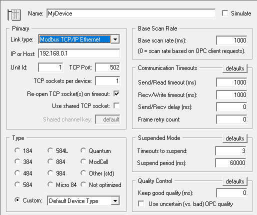
Give the Device a name and specify “Link Type” as Modbus TCP/IP Ethernet or *Modbus Serial RS-323.
NOTE: A COM/Serial port should have been defined if selecting Modbus Serial RS-323.
Device Link Type Settings
NOTE: These settings must match the settings of your Modbus device.
Select IP or HOST for Modbus TCP/IP Ethernet or COM Port if defining a Modbus Serial RS-232 device.
Device Link Type Settings/ IP or Host Setting
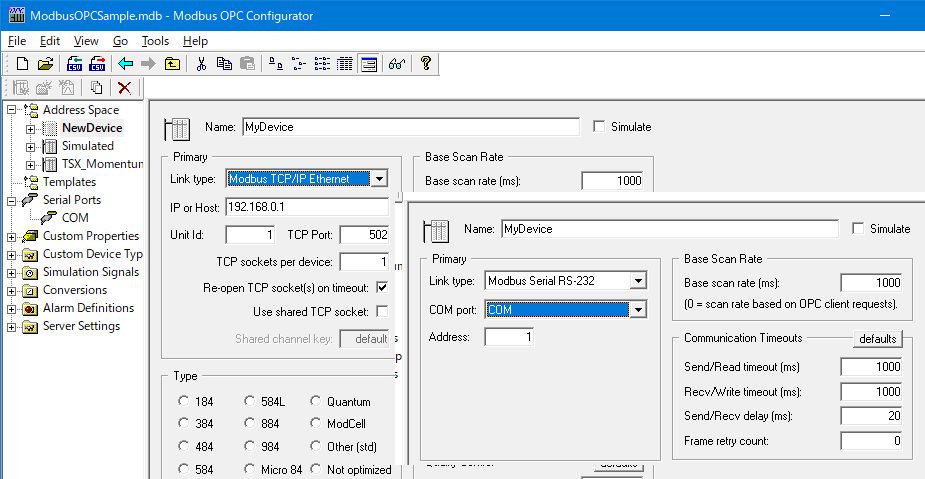
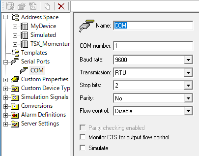
If selecting Modbus Serial RS-323, then define a Serial port with properties matching to Serial device as shown in the following image.
Serial COM Port Setting
Then, select the Device (Radio Button) Type if it is listed under “Type”, otherwise select “Custom” and press the “Apply” button when you are done.
Device Type
Right-click on the device that you have just created and select New > Data Item.
Data Item
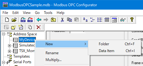
NOTE: You can use the “Folder” option to arrange data items more efficiently.
Give the data item a name and set its properties like Modbus Data Type and Device Address, then click on “Apply” when you are done.
You can create a Temperature tag as shown in the following image if you wish.
Temperature Tag Settings
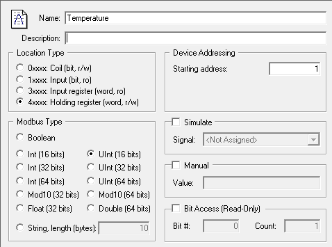
Similarly, you can create additional data items, then click on “Apply” when you are done.
If you want your data items to generate OPC Alarms, check “Generate Alarms“ and select “Limit” or “Digital” based upon your Modbus Data Type along with any desired additional properties.
You may have to define additional “Limit” and “Digital” alarms under  in Server configuration for multiple OPC Data Items.
Generate Alarms
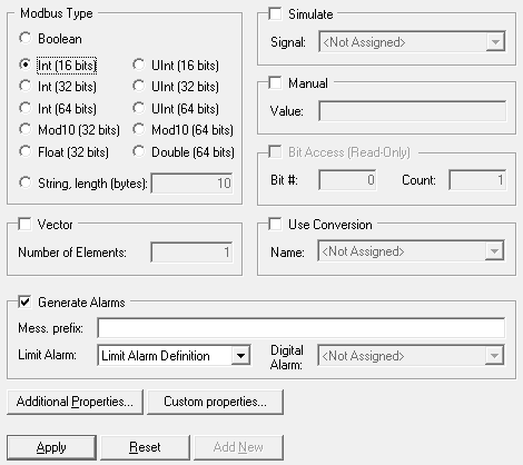
NOTE: You can connect any industry standard OPC Alarm & Event client such as “ICONICS AlarmWorX32 Viewer” to view alarms from Modbus A&E server.
Your configuration is ready and now you can monitor OPC data items by clicking on the Monitor View button  and selecting a folder or data item on the side panel of your configuration.
Monitor View
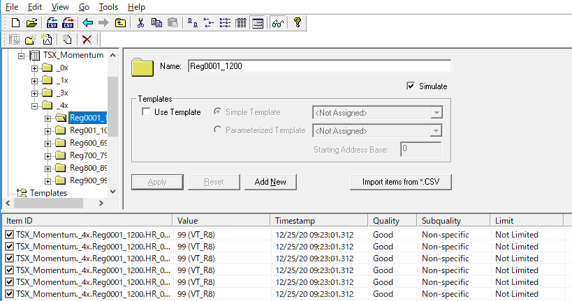
You can exit the configurator and use an OPC client to browse the Modbus OPC Server and OPC tags.
The Server Settings tree in the Modbus OPC Server Configurator allows you to make changes to the server itself, specifically:
Threading
Trace
Statistics
Online Changes
Sockets
The Threading configuration allows you to specify the initial and maximum number of threads created by the OPC server.
Threading Options
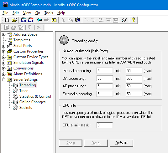
In Modbus version 3.6 or later you can enable XML Tracing to diagnose communication issues with your configuration. To do so, check the “Enable XML tracing” box and change the other trace settings as desired.
Under the Statistics & Control page, you can enable runtime statistics and control items to achieve the following.
Statistics & Control Options
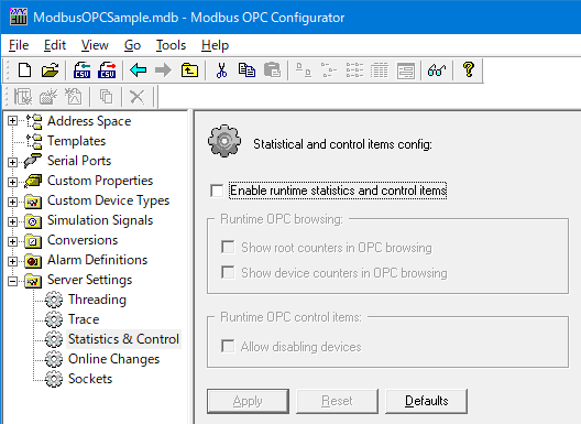
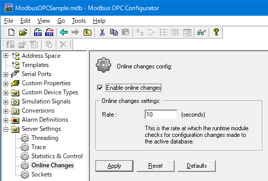
The Online Changes dialog allows you to define the rate at which the Modbus runtime checks for configuration changes made to the active database.
Online Changes Options
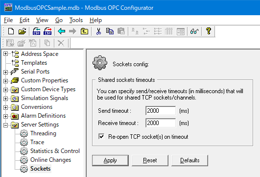
You can specify send/receive timeouts (in milliseconds) that will be used for shared TCP sockets/channels.
Sockets Options
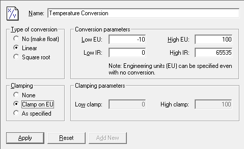
Scaling is an advanced capability of the Modbus OPC Server. It is used to convert raw device data into meaningful engineering data. In the following example, we will demonstrate how to convert a temperature sensor with a value from 0 to 65535 to have engineering values from -10 to 300 degrees Celsius.
Start the Modbus OPC Configurator.
In the left-hand pane, right-click on the Conversions folder and select New > Conversion.
Set the High IR (Instrument Range) to 65535.
Set the Low EU (Engineering Units) to -10 and the High EU to 300.
Temperature Conversion Properties
Click “Apply” when you are done.
If you have followed the example and created a Temperature tag in the previous section, select the tag.
In the tag configuration, check Use Conversion and select the Temperature Conversion we have just created.
Click on “Apply” when you are done.
See Also:
Modbus Point Manager Quick Start