Modbus Point Manager supports Modbus Ethernet TCP/IP Devices. The functionality of the Modbus Point Manager is based on ICONICS' standalone Modbus OPC Server, providing functionality such as:
Configurable Device Types (Parameters)
Multiple Sockets Per Device
Protocol Diagnostics
Runtime Statistics
Performance Counters
Address Space Template
Communication channels - fully configurable
Asynchronous non-blocking communications
Optimal (configurable) Modbus messaging
Advanced OPC data quality and data conversion to client's request.
Supports multiple multi-drop I/O devices.
Supports all popular PLC and RTU data types.
Internal simulation for configuration and testing.
Tag multiplier allows you to create hundreds of tags in seconds.
Support for OPC Data Access (DA) and Alarm & Events (AE) specifications.
Flexible engineering units and signal ranges.
TraceWorX diagnostics support (logging data into XML file)
Sample OPC Client
Start Modbus Point Manager by opening Workbench and going to Data Connectivity > Modbus.
Modbus Provider in Workbench
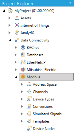
In the Modbus configuration, a device represents a hardware device that communicates with the OPC server over TCP/IP.
The Address Space in the Modbus configuration, shown in Figure 2, sets the properties and connection parameters for the following items:
Devices
Folder Item
Data Items
Address Space
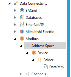
The Modbus configuration offers several levels in its hierarchy. The Modbus module uses the terms Folder and Data Item.
A folder can contain additional folders and data items. The data items are always the branches in the tree control hierarchy. Setting up a device requires configuration of its unique address, type, timeouts, and optimization parameters.
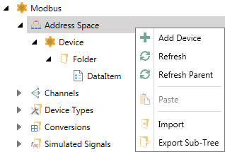
From the Project Explorer, click on Address Space, then Add Device, as shown in the following image.
Adding a New Device
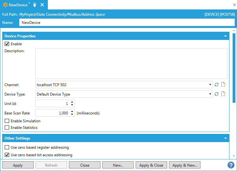
Device Properties:
Description - Enter a description of the device in the text entry field. This will help to differentiate individual devices when multiple items are configured.
Enable - Click this checkbox to enable the selected device.
Channel - Use the pulldown menu to select from listed Channels. Click on the button to refresh the list. Click on the button to open an additional window containing the selected Channel's properties.
Device Type - Use the dropdown menu to select a Device Type from among those listed (Default Device Type, Ideal, Micro 84, ModCell, Modicon 184, Modicon 384, Modicon 484, Modicon 584, Modicon 584L, Modicon 884, Modicon 984, Quantum, or Simple).
Unit Id - The Unit Identifier field may be used to communicate via devices such as bridges.
Base Scan Rate - This sets the rate, in milliseconds, at which the data will be polled from the device. Fast scan rates may have impact on a device's responsiveness.
Enable Simulation - Click this checkbox if this device should be considered as simulated only.
Enable Statistics - Click this checkbox to enable statistics.
Other Settings:
Use zero based register addressing - Enables "Zero vs. One"-based addressing of coils and registers (at Data Item level).
Use zero based bit access addressing - Enables "Zero vs. One"-based register bit-access addressing (at Data Item level).
Disable tags at invalid addresses - Enables disabling of polling of tags that are detected at invalid device addresses.
Use uncertain (vs. bad) OPC quality - Allows for reporting of data with uncertain OPC quality when the device is disconnected, and good data was previously known.
Use register mask write (Modbus Fnc 22) - Enables writing of bit-access data into a device using Modbus function 22 (Mask Write Register). The device/vendor must support this Modbus function.
Use single coil write (Modbus Fnc 05) - Uses Modbus function 05 (Write Single Coil) to write into a single coil. Otherwise, Modbus function 15 (Write Multiple Coils) will be used. Note that the Modbus function 05 may not be implemented by all Modbus devices/vendors, while Modbus function 15 is usually implemented by all devices/vendors.
Use single register write (Modbus Fnc 06) - Uses Modbus function 06 (Write Single Register) to write into a single register. Otherwise, Modbus function 16 (Write Multiple Registers) is used. Note that Modbus function 06 may not be implemented by all Modbus devices/vendors, while the Modbus function 16 is usually implemented by all devices/vendors.
Template:
Use Template - Click this checkbox if you wish to use a preconfigured template to set the properties for your selected device. Once checked, this activates the nearby pulldown menu where you can select from existing Templates. Click on the button to refresh this list with any recent changes to the listed Templates.
Suspended Mode Settings (Channel-level override):
Override Suspended Mode - Click this checkbox to set the suspended mode setting to override.
Timeouts to suspend - Sets the number of timeouts before suspending.
Suspended period - Sets the suspension period.
Once you have completed modifying your settings, click Apply (or Apply & Close).
Device Properties
Right-click on the device that you have just created and select Add Data Item.
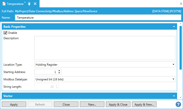
Give the data item a name and set its properties such as Modbus Datatype and Device Address then click on Apply. Your Modbus data item is now ready to be used in OPC client applications like GraphWorX64.
Data Item
Most commonly available Modbus devices are already configured in the Modbus Point Manager’s Device Type list. However, if your device is not present in the list it can be added.
Right-click on Device Types and select Add Device Type.
Adding a Device Type
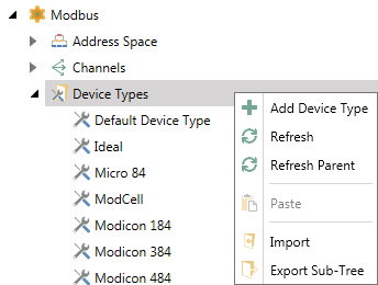
In the Name field, specify a name for the new device type and select additional properties for the device type as following:
Block Parameters - Each number is the maximum amount of data that can be transferred in one/read write message. Specifying 0 (zero) instructs the server to use single read/writes only.
Coils (read)
Inputs (read)
Input registers (read)
Holding registers (read)
Coils (write)
Holding registers (write)
Block Unused Data Optimizations - Each number indicates how much unused data can be transferred in one message to merge addresses that are close but not adjacent.
Unused bits (coils, inputs)
Unused words (registers)
Swap Options:
Swap bits inside words
Swap bytes inside words
Swap words inside dwords
Swap dwords inside 64-bit registers
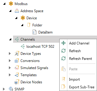
The Channels node within the Modbus Point Manager allows you to set a new channel where you can set the Channel Type of Modbus TCP/IP Ethernet. The selected Channel Type will automatically change the list of properties to complete. Set Channels can then be selected from within Device properties.
Modbus New Channel
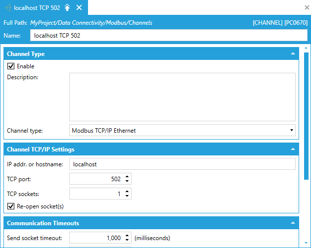
Channel Type:
Description - Enter a description of the channel here if you want to differentiate it from any additional channel.
Enable - Click this checkbox to enable the channel.
Channel Type - Use the pulldown menu to select Modbus TCP/IP Ethernet. The remainder of the properties to complete will update according to the selection.
Channel TCP/IP Setting
IP address or hostname - Enter the IP address or hostname in the text entry field.
TCP port - Enter the TCP port number in the text entry field.
TCP sockets - Enter the TCP sockets in the text entry field.
Re-open socket(s) - Click this checkbox to close and reopen the TCP socket(s) when a timeout is detected.
Communication Timeouts
Send socket timeout - Enter the duration of the timeout in the text entry field.
Recv socket timeout - Enter the duration of the timeout in the text entry field.
Send/Recv delay - Enter the send/receive delay in the text entry field.
Frame retry count - Enter the retry count in the text entry field.
Suspended Mode Settings
Timeouts to suspend - Enter the number of timeouts to suspend in the text entry field.
Suspended period - Enter the amount of time in the text entry field (in milliseconds) for the suspended period.
TCP Channel
See Also: