menu pulldown button in the Grid/Ruler section of the ribbon.
A Parallel Projection grid is defined by a width and two angles, rather than a standard width/height rectangular grid.
Isometric, Dimetric and Trimetric are all types of Axonometric projections, which are also types of Orthographic projections. Axonometric is a type of Parallel Projection. Oblique is its own type of Parallel Projection.
Isometric - 30 degrees and 30 degrees
Dimetric - 26.565 degrees and 25.565 degrees (aka "pixel-friendly" isometric because it produces 2:1 line slopes)
Trimetric - any two angles from 0 to 89 degrees (ex. 30 and 5)
Oblique - 0 degrees and typically 45 degrees
Users can select a Parallel Projection layout via the followings steps:
menu pulldown button in the Grid/Ruler section of the ribbon.Selecting a Parallel Projection Layout
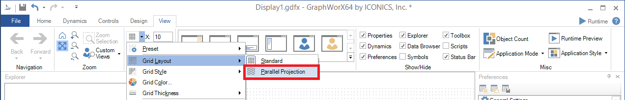
The display portion of the GraphWorX64 window will change accordingly.
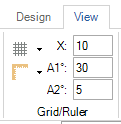
Once the Grid Layout has been changed to Parallel Projection, you can then configure the grid angles. You may notice that the Grid/Ruler section of the View ribbon now contains additional text entry fields, as shown below.
|
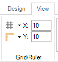
Grid/Ruler Section of the View Ribbon with Standard Grid Layout Selected |
Grid/Ruler Section of the View Ribbon with Parallel Projection Layout Selected |
|
|
|
You can then enter the A1° (Angle 1) or A2° (Angle 2) in each respective text entry field.
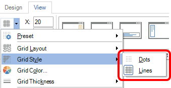
Users have the option of using either dots or lines within their grid. Lines can sometimes work better for Parallel Projection grids, as they often make it easier to see the angles.
To make a selection, click on the button in the Grid/Ruler section of the View ribbon and then on Grid Style, as shown below. You can then select either Dots or Lines.
Grid Style Selection
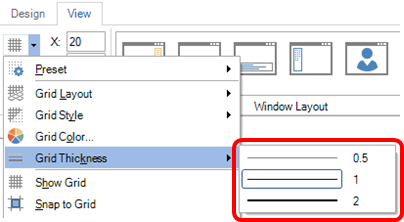
Users can change grid/line dot thickness for visibility purposes. For instance, grid lines thinner than 1 pixel or dots thicker than 1 pixel might be required.
To make a selection, click on the button in the Grid/Ruler section of the View ribbon and then on Grid Thickness, as shown below. Depending on the Grid Style you selected (Dots or Lines), you can then select the thickness by the visual or numeric indicator (in the example below, the Grid Style was selected as Lines).
Grid Thickness Selection
For Parallel Projection grids, multiple grid snapping options are required. The corners work well for an Oblique layout. Edge midpoints work well for Isometric and Dimetric layouts. Shape vertices work well for Trimetric.
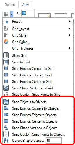
Users can select from multiple options, shown below, including:
To utilize any of these options, click on the button in the Grid/Ruler section of the View ribbon and then on any of the options as shown below.
Grid Snapping Options

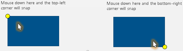
It is useful to understand which corner/edge/vertex will snap when moving an object. The corner/edge/vertex closest to where a user presses the mouse button down to drag will be the point to snap to the grid, as shown below.
Expected Corner/Edge/Vertex Snapping
An on-screen snapping indicator shows users which point was snapped, as shown below.
On Screen Mapping Indicator Examples

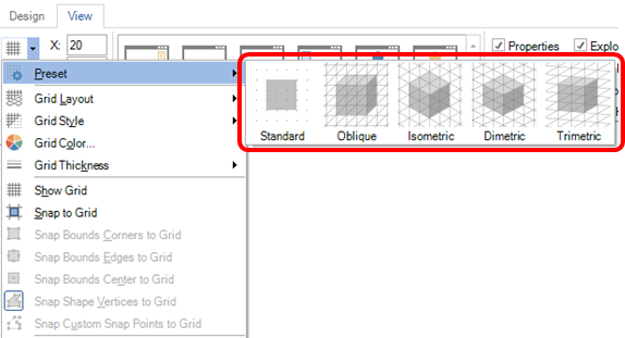
Grid Presets provide one-click options to change multiple settings for common grid configurations. Users can change layout, angles, style, thickness and snapping all in one click, as shown below.
Preset Menu Option
Users may want to skew objects/images to precisely match (or be a multiple or fraction of) the grid angles. "Freehand" skewing via the "onscreen drag handles" is not precise. A new setting, shown below, allows for typing in precise skew angles.
Precise Transforms via 'Skew By' Properties in 'Transform By' Window
![]()
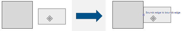
Grid snapping is good for drawing isometric symbols, but different symbol sizes and shapes can make aligning symbols together a challenge - even with a grid. Users can now utilize a feature that provides snapping of objects/symbols together independently of a grid.
Object to Object Snapping Example
Users can select from multiple options, shown below, including:
To utilize any of these options, click on the button in the Grid/Ruler section of the View ribbon and then on any of the options as shown below.
Object Snapping Options
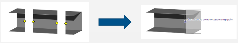
Users may wish to include very specific snapping behavior for certain types of symbols. For example, a user may want to snap only the ends of ducts together, as shown below.
Custom Snap Point Example
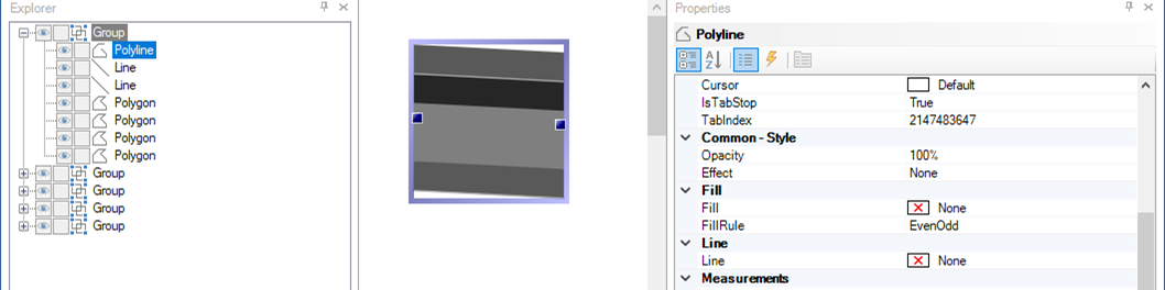
Custom snap points can be defined using "invisible" (Fill = None, Line = None) Polylines inside a symbol, shown in the example below.
Custom Snap Points with 'Invisible' Polylines
Sometimes gapless objects might not be required. Click HERE for more info.
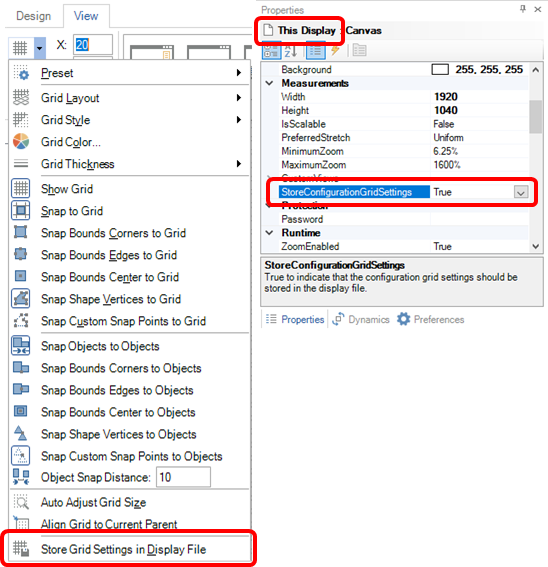
In previous versions of GraphWorX64, grid settings were an application preference, not saved within a display file. Parallel Project displays require very specific grid settings for subsequent modifications to align properly. It could be difficult to reconstitute just by looking at the display. With multiple new grid options available, manually resetting them when editing different displays would be cumbersome. There is now a new option to save the grid settings in the display file, as shown below.
Store Grid Settings in Display File Menu Option
See Also: