(in the Primitives section). Use its properties to cap the ends, change the radius, and alter the pipes' appearance. You can also easily animate an object so that, during runtime, it moves along the path of a 3D pipe.
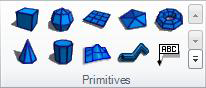
Use the pipe primitive to add sections of pipe to a 3D view which you connect into a network of pipes, for example, to expose valves and water sensors. You can add a pipe primitive to your 3D view by clicking the Home ribbon's pipe icon (in the Primitives section). Use its properties to cap the ends, change the radius, and alter the pipes' appearance. You can also easily animate an object so that, during runtime, it moves along the path of a 3D pipe.
|
|
Note: In 2D displays, it is the Pipe Control that is used for adding pipes, not the pipe primitive. |
This topic describes how to do the following:
Add a 3D pipe primitive and adjust its coordinates
Delete a bend from a 3D pipe
Use a pipe as the path for an object that you have animated with a location dynamic
Also, you can write a script that creates pipes dynamically during runtime. An example of such a script is provided in the GENESIS64 GenDemo.
To add a pipe to a 3D view:
If you want the pipes to adhere to a grid structure, adjust the grid in the 3D work area and turn on the Snap to Grip feature. For additional information, refer to Grid Options in 3D.
Add a pipe primitive to your 3D view by clicking the pipe icon in the Primitives section of the 3D Home ribbon. The pipe primitive will appear in your 3D view, and you will see it listed in the Explorer and the Properties tab.
Use the tools in the Home ribbon's Manipulator section to change the shape, size, and orientation of the pipe; this is easier than using the pipe's properties to do the same thing. For help using these tools, refer to Manipulator Section of the 3D Home Ribbon.
If you want to bend the pipe in its middle:
Double-click the pipe until you see a brown line that forms a path along with the Move manipulator.
Click on the spot where you want to add a bend; this adds a round, red handle at that spot with a Move manipulator. Click here to see an illustration. (If you inadvertently add a bend where you don't want one, right-clicking the bend removes it.)
Drag the Move manipulator with your mouse to create a bend in the path. (For help using the manipulator, refer to The Move Manipulator.)
Use the Snap to Grid feature to control the angles at which the pipe bends. The grid's cell size will affect the length of pipe between bends if you are using the Snap to Grid feature. (Note that the Angle Snap grid option controls the pipe's rotation, not the angle of its bends.)
To make sure your pipes bend on the correct plane, use the tools described in Navigating in a 3D Viewport and the perspective buttons described in View Section of the 3D Home Ribbon.
Each bend's XYZ coordinates are written to the pipe primitive’s Points property. You can manually adjust the coordinates to specify their exact coordinates and to force pipes to align exactly inside the 3D grid. For example, you can manually adjust bend points so that they align to .0 or .5 line on the grid and this will make the pipes align also. If a coordinate is 3.9289347236, you can change it to 4.0; or if a coordinate is -0.492087102346, you can change it to 0.5.
As shown in the example below, before the coordinates are adjusted their slight misalignment is barely noticeable; after the coordinates are adjusted, the pipes align to perfectly to the grid. If the pipe network you are creating is vast, this slight misalignment might make a difference to you. If it doesn't you don't need to adjust the coordinates.

To make each point's coordinates more exact, follow these steps:
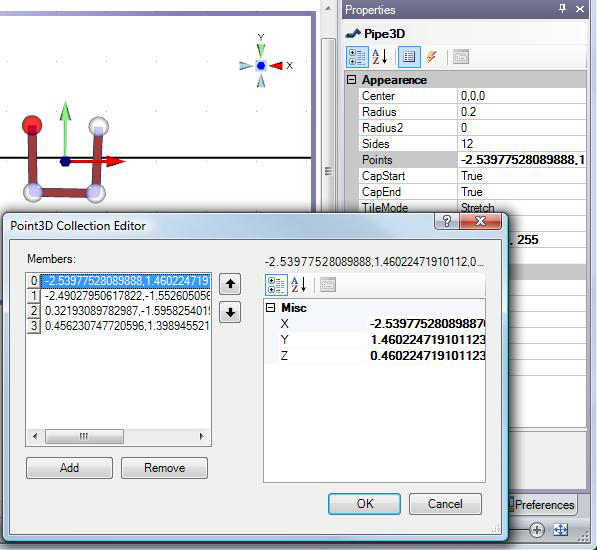
Go to the Points property and click the ellipsis ![]() button to open the Point 3D Collection Editor dialog box. For an example of a pipe before the adjustments are made, click here.
button to open the Point 3D Collection Editor dialog box. For an example of a pipe before the adjustments are made, click here.
From the Members list, select the point you want to adjust.
Change its X, Y, and Z coordinates in the Misc section, on the right. For an example of the final version of these adjustments, click here.
To add a bend at the end of a pipe:
Select the pipe in the object Explorer.
On the Properties tab, go to the pipe's Points property and click the ellipsis ![]() button. This opens the Point 3D Collection Editor dialog box.
button. This opens the Point 3D Collection Editor dialog box.
Click the Add button. This adds a new line to the bottom of the Members list, placing a new bend at one end of the pipe. (You can place the bend at the other end of the pipe by clicking the up arrow button to move the new bend to the top of the list.)
Click OK to close the dialog box.
Select the new end of the pipe and move it to the desired location. (You may need to click off the pipe, then reselect the pipe first.)
Use the pipe's properties to make other changes to the pipe. Many of the pipe's properties are described in Common Properties for All 3D Primitives.
Establish the entire pipe network by adding more pipe primitives, models, and other primitives as needed.
You can also:
Add a dynamic from the Dynamic ribbon
Move, scale, rotate, transform, or duplicate the pipe
Change the look (color, texture..)
To remove a bend or handle from a 3D pipe:
Select the pipe in the object Explorer.
On the 3D pipe's Properties tab, click on the Points properties then click the Points property's ellipsis button. The Point3D Collection Editor dialog box appears. Each point is listed in the Members list; the top and bottom points mark the start and end points of the pipe.
Select the point you want to remove, then click the Remove button.
You can also easily animate an object so that, during runtime, it moves along the path of a 3D pipe. To set a location dynamic to follow a pipe's path:
In the 3D viewport, create the 3D pipe that you want the object to move along. Make sure you create the pipe in it's entirety, so that the entire length of pipe is complete.
Select the object you want to animate so that it follows the pipe's path.
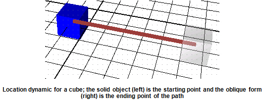
Click the Location button in the Position section on the Dynamics ribbon. This creates a Location dynamic. Initially, a path from the selected object to an oblique form of the object appears. Ignore this path.
Select both the object and the 3D pipe primitive.
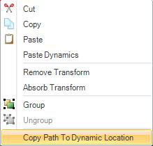
Right-click to display a pop-up menu then select Copy Path to Dynamic Location. This adds the pipe's path to the object's location dynamic and moves the object to one end of the pipe object. The two objects remain in the Explorer as two separate objects.
|
|
Note: The path gets automatically written to the Location dynamic’s 3DPath property. Don’t set the 3DPath property manually. |
Using the Dynamics tab, set the Location dynamic’s properties. These properties are described in Location Dynamics Properties in 3D.
See also: