Alarm Tags
An alarm tag is a single object for OPC alarm information; it consists of an OPC tag source to be monitored, and at least one condition that determines an alarm state. You create an alarm tag so that the OPC tag source can be monitored using any of the following:
- A chart or grid in an AlarmWorX64 Viewer definition
- A SmartPin on an EarthWorX map
- A 3D annotation in a GraphWorX64 display
When establishing an AlarmWorX64 Server configuration (see Database Configurations), you must define the alarm tags for that configuration. OPC alarm tags can also be grouped into areas, to make them easier to find and work with; for more information, refer to Areas. Each alarm tag that you create contains information about how its alarm is triggered. There are multiple types of OPC alarms that you can set, including deviation, limit, rate of change, and digital alarms.
To help you define alarms for OPC tags, you can create templates. The steps for defining a template are the same as for defining an alarm. The difference is that if you have templates in place, you can:
-
Create alarm tags using a template as their basis; you can create them one at a time or you can create multiple similar tags all at the same time.
-
Easily maintain the alarm tags because instead of maintaining each alarm tag you can maintain the template that created them.
An alarm's visual appearance when it is triggered during runtime is configured when the alarm tag is added to an alarm grid, as described in Grid Options in an AlarmWorX64 Viewer. Some alarm tags may require secured acknowledgement by a user or group that has legitimate credentials to acknowledge them. You can protect such alarms by assigning them to users or groups in Security Server (see Security Privileges for Users and Groups for more information), and can even require a user login for critical alarms (see Security Server' Global Settings for more information).
The remainder of this topic describes how to:
Important Side Note about Alarm Calculation
It is important to note that an OPC tag's alarm states are calculated with each update of the OPC tag. This means that alarm tags that have multiple OPC tags associated with a state will be calculated once for each OPC tag update. For example: A Limit alarm has an OPC tag for the OPC Input field and another one defined for the LoLo field. Both tags change value and are updated to the alarm server simultaneously. The server then calculates the limit value once for the OPC Input field and once for the LoLo field.
The sequence in which fields are calculated is random; it is determined by the sequence in which they are placed in the update queue. Normally this is not a concern. However, this can cause alarms to occur because of "noise" situations. For example, if the LoLo value changes from 5 to 15 and the OPC Input value changes from 6 to 16, an alarm might report if the new LoLo value is calculated before the new OPC input value, even though these two numbers changed "simultaneously." This can be especially true when using alias values, as each of the OPC data inputs will be calculated individually.
|

|
Note: The following categories are not used in the AlarmWorX64 Server : OPC Server Error, System Configuration, and System Messages. For more information, please refer to the OPC Alarm and Events specification at www.opcfoundation.org. To download the current OPC UA specification on alarms click here.
|
Return to top
Creating One Alarm Tag at a Time
You create an alarm tag using AlarmWorX64 Server:
-
Right-click the database configuration, then select the Tag command from the context menu.
The new tag appears at the bottom of the configuration tree with the name New Item. Also, the AlarmWorX64 Server Tag form opens; here you can set the characteristics of the alarm that will monitor incoming values from the OPC tag.
-
Enter the name of the tag into the Name text box; this name replaces the default name of New Item. The box to the right of the Name box shows the date and time the tag was last modified.
-
Click the ellipsis button  next to the OPC Input text box and use the Data Browser to select the path to the OPC tag that you wish to monitor. The calculation of alarms can be based on OPC tags and or on expressions.
Since OPC UA doesn't store alarms in a tree type hierarchy you may find it more convenient to browse for alarms using the Mesh view of the Data Browser; if you subscribe to a particular alarm you will see any of the other alarms or sub-areas that are beneath that alarm or area in the alarm hierarchy.
-
If you want to use a template to create the alarm tag, select the template from the Template drop-down list. Once you do this, all fields for the tag are populated with the template's values. You can use the template values or use different ones. [Note: You can also Create a Tag from a Template directly from the Project Explorer].
|

|
Important: Values populated by the template are highlighted in pink; if you type a different value, the highlighting disappears. Fields that are highlighted in pink can be maintained from the template and will change if they are changed in the template. Once you change a value causing the pink highlighting to disappear, the field can no longer be maintained from the template. For more information, refer to Alarm Templates.
|
-
Go to the General tab. Here, all properties apply to all alarm types.
-
Enter 1 into the Enabled text box to activate the tag so that it is monitored and can be used as an alarm. Alternatively, you can click the ellipsis button to create an expression that evaluates to True or 1.
|

|
Tip: You may prefer to enable and disable the alarm based on a condition. For example, you may not want to monitor water pressure when the valve is shut off because the drop in pressure would trigger the alarm. In this case, you can specify the tag for the valve’s reading in the Enabled field such that when the valve is open (1) the alarm is enabled, but when the valve is closed (0) the alarm is disabled.
|
-
Enter the file to display in the Default Display for the selected tag by clicking the ellipsis button and browsing for a file. This is the display for the alarm, either in an AlarmWorX64 Viewer or a GraphWorX64 display.
-
Enter a description of the alarm's purpose in the Description text box. Although this field is optional, it may be a critical component later on for operators need to work with it but who are not familiar with its origins. Make the description complete so that the alarm's purpose is clear and can be understood by others who will need to work with it and maintain it.
-
Optionally, you can specify a delay in the Delay (seconds) field. A delay suppresses alarm reporting for a period of time after it is detected. If the alarm condition still exists after the delay, the alarm is reported. Using a delay is helpful for offsetting readings that fluctuate wildly or sensors that sometimes return faulty readings; you can also use it with equipment that typically returns to normal quickly. If you leave this field empty, the alarm is reported as soon as it is detected.
-
Specify the alarm's Base Text, which is the message that appears with the alarm when it is displayed. It is important to enter base text information for your users along with Help Instructions. The text and instructions should indicate the alarm's state, and can include informational text to runtime operators for responding to the state, such as providing phone numbers or contact information or listing steps for the operator to follow.
|
|
Note: The Base Text field automatically adds a single space at the beginning of the text string, so you should be aware of this when filtering alarms.
|
-
The Enable Clear checkbox enables the Clear state for a particular alarm. The Delay On Alarm Only checkbox ensures that the delay setting only affects going into alarm state. The Exclude Equal To checkbox causes generation to use the > or < for comparison instead of <= and >=.
-
If the alarm tags that will be created using this template all belong to the same area or areas, and areas have already been created, you can click the Add button to display the Areas dialog box; here you can select areas that alarm tags are to be added to. The areas display at the bottom of the tab. To see the area that the tag belongs to, select the area then click Jump to Area. The Area expands in the navigation tree, showing you the tags for the area.
-
Click the Alarms Limit/Digital, Alarms Deviation/Rate of Change, Alarms Rate Limit/Trigger Limit, and/or Related Values tabs to create the type of alarm that you wish to create. These different alarm types and all four tabs are described below in more detail. For each alarm tag, you must define the conditions under which an alarm exists. You can define the following types of alarms, which are event categories named after conditions. Click on the hyperlink to see how to configure the alarm condition.
-
-
Deviation alarm: Triggers an alarm if the difference between two input values exceeds the high or low limits specified in the alarm tag.
-
Digital alarm: Triggers an alarm if the comparison between the Alarm State Value (specified in the alarm tag) and the input state is TRUE.
-
Limit alarm: Triggers an alarm if the input value exceeds the high or low limits specified in the alarm tag.
-
Rate of Change alarm: Triggers an alarm if, over the course of a second, an input value changes at a rate greater than or equal to the limit specified in the alarm tag.
-
Rate Limit alarm: Triggers an alarm if, over the course of a second, an input value increases or decreases by an amount that exceeds the high or low limits specified in the alarm tag.
-
Trigger Limit alarm: Triggers an alarm when the OPC tag's value changes. This alarm requires a runtime operator's acknowledgement.
|
|
Note: The Limit, Deviation, and Rate Limit alarms classify the tag as an Analog tag. The Rate of Change, Digital, or Trigger Limit alarms classify the tag as a Digital tag. A tag that a mix of alarms is classified as an Analog/Digital tag.
|
-
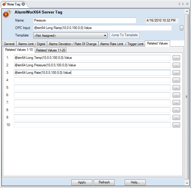
On the Related Values tab, specify up to 20 OPC tag values to be collected when an alarm occurs. Collect this information when you need to troubleshoot the circumstances that caused an abnormal condition. For more about this tab, refer to Related Values at the bottom of this topic.
-
When you are done, click Apply to create your alarm tag.
-
You can protect the alarm at runtime by assigning it to users or groups in Security Server. See Security Privileges for Users and Groups for more information.
-
You can require a user login for a critical alarm. See Security Server' Global Settings for more information.
You can edit an existing alarm tag by double-clicking on the tag in the tree control or by right-clicking the name and selecting the Edit or Edit on New Tab command in the context menu. You can also use the Copy and Paste commands to create copies of an alarm, or Cut and Paste to move an alarm from one database configuration to another. The context menu also is where can delete an alarm.
Return to Top
Creating a Tag from a Template
In addition to creating a single tag from the Tag command from the context menu within the Project Explorer, you also have the option of creating a tag from an existing template. This action will create the Alarm Tag according to the selected template with no default values set for the Alarm Tag, so all the values are initially set from the template. This create "New Tag from Template" action will create a new alarm tag that include all the set values pre-set in the template.
-
Right-click the database configuration, then select the Tag from Template command from the context menu.
-
The Alarm Tag Templates Selector window appears, containing the Templates that have previously been set within the Templates branch of the Project Explorer within the AlarmWorX64 Server provider in Workbench/GENESIS64. Select your desired template from the list then click on OK to proceed.
-
The New Tag will appear beneath the database configuration branch of the Project Explorer. The AlarmWorX64 Server Tag properties window will open in the right-side pane of the Workbench.
|
|
Important: Values populated by the template are highlighted in pink. If you type a different value, the highlighting disappears. Fields that are highlighted in pink can be maintained from the template and will change if they are changed in the template. Once you change a value causing the pink highlighting to disappear, the field can no longer be maintained from the template. For more information, refer to Alarm Templates.
|
- Proceed from Step 5 from Creating One Alarm Tag at a Time above.
Return to top
Creating Several Alarm Tags at Once
To create several alarm tags at once, follow these steps:
-
Before you begin, you must have one or more templates that you will be using to define the alarm tags. For more about such templates, refer to Alarm Templates.
-
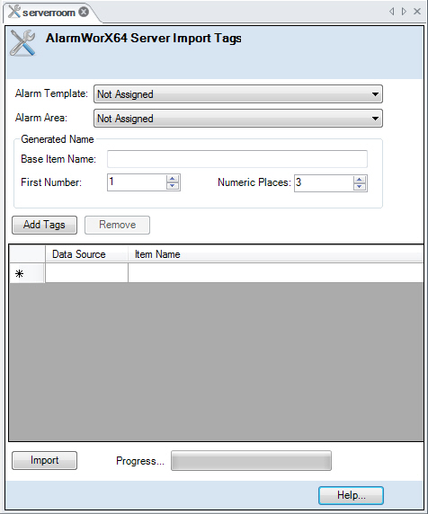
Right-click the database configuration in which you want to create the alarm tags, then select the Tag Import Wizard command from the context menu. The AlarmWorX64 Server Import Tags form opens.
-
From the Alarm Template drop-down list, select the template you want to use for creating alarms for the multiple OPC tags.
-
Optionally, if you want to assign the new alarm tags that you create to one area, you can select the area from the Alarm Area drop-down list. (For information on how to add areas later, refer to Areas and Their Alarm Tags.)
-
Enter the Base Item Name. This is the name that will be assigned to all of the alarm tags that are created as part of this procedure. A number will be appended for each alarm tag so that each alarm tag's name is unique. Numbers increment by 1. If you leave this field empty, the name that gets assigned to each alarm tag is its OPC tag path. (You can rename tags later.)
-
Click the Add Tags button. This opens the Data Browser where you can navigate to the OPC tags you are defining alarms for.
-
Select the OPC tags, then click OK. The tags are listed on the form in the Data Source column. Note how each alarm tag's Item Name is the Base Item Name plus a number; numbers increment by 1 so that each alarm tag's name is unique.
-
You can change the name of each alarm tag, if you like, by clicking in the Item Name column and typing the new name for the tag. Item names must be unique.
-
To add more tags, repeat Steps 6, 7, and 8. To remove tags from the list, click beside the item in the left column, then press the Delete key on your keyboard. (To select multiple lines, press the Ctrl or Shift key while clicking.)
-
When the list of OPC tags is complete, click the Import button. This defines each OPC tag as an alarm tag, and applies the template's definitions to each new alarm tag. When the alarm tags have been created, a Results dialog box appears.
-
Review the results in the dialog box and click OK when you are done. The new alarm tags are listed in the Project Explorer in the configuration tree where you created them.
-
At this point, you can:
-
create more alarms,
-
edit individual alarm tags, as necessary to override values provided by the template, and
-
add the new alarm tags to areas (as described in Areas in AlarmWorX64 Server).
-
Set up protection for alarms by assigning them to users or groups in Security Server. See Security Privileges for Users and Groups for more information.
-
Require a user login for critical alarms. See Security Server' Global Settings for more information.
As OPC tags are added to AlarmWorX64 Viewer displays, the alarm tags defined for the OPC tags determine whether alarms report.
Return to Top
Limit Alarms
A Limit alarm reports an incoming reading that exceeds a high or low threshold. Use a Limit alarm for an OPC tag whose readings have static limits that you do not want exceeded, such as temperature gauge, a counter, or a pressure gauge. To create a Limit alarm for the OPC tag, follow these steps:
-
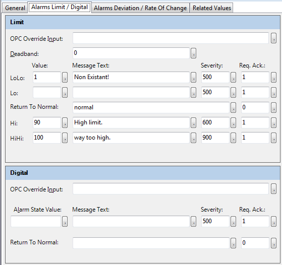
Use the Alarms Limit/Digital tab of the Alarm Server Source form, and set options in the Limit pane at the top.
-
By default, this alarm reads the values of the OPC tag you specified in the OPC Input field. You can overwrite this tag by specifying a different tag in the OPC Override Input field in the Limit pane.
-
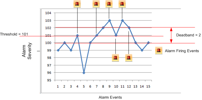
In the Deadband field, specify a buffer amount surrounding a limit in which the alarm will not signal. The deadband value applies to converted analog values. The deadband value is required and is calculated on borderline alarming limit values to prevent repeated alarm cycles. An alarm series with a threshold of 101 (when the alarm triggers) and a deadband of +/-1 or 2 triggers in the instances with the alarm icon. Click here to see an example.
-
As needed, enter values in the Value fields of LoLo, Lo, Hi, and/or HiHi. Use these fields to provide the acceptable limits of the tag’s readings. You can set one, two, three, or four limits, each with its own warning or alert text, severity level, and acknowledgement requirements. The alarm's appearance when it is triggered during runtime is configured when the alarm tag is added to an alarm grid, as described in Grid Options in an AlarmWorX64 Viewer.
-
-
HiHi: Triggers an alarm if the value is greater than or equal to the HiHi limit specified in the Alarm Server configuration.
-
Hi: Triggers an alarm if the value is greater than or equal to the Hi limit specified in the Alarm Server configuration.
-
Lo: Triggers an alarm if the value is less than or equal to the Lo limit specified in the Alarm Server configuration.
-
LoLo: Triggers an alarm if the value is less than or equal to the LoLo limit specified in the Alarm Server configuration.
The values that you enter are compared to readings from the tag. For example, a value of 10 for LoLo is compared with the value of the OPC tag to determine if the alarm is in LoLo state. The alarm is triggered when the OPC tag's value exceeds the high or low limits.
-
For each Value field (LoLo, Lo, Hi, HiHi) that you are using, specify the following information:
-
|
|
Note: If you don't specify message text, by default the OPC subcondition name and the OPC condition name are used. For example, a LoLo alarm will post a description of LoLo limit.
Note: If no value is specified in the configuration and the subcondition is later enabled using the AlarmWorX Server DA tags, the configured message text will not be used. The default message text will be used instead. This is because the alarm server assumes that alarms with no value are not in use and it will not load them into runtime.
|
-
-
Severity is the OPC-defined value for the alarm's priority. The valid OPC severity range is 0 (lowest) to 1000 (highest). For more about severity codes, refer to the Error Reporting table.
-
Requires Ack determines whether the alarm requires a user's acknowledgement. If the condition requires user acknowledgement, enter 1. If it doesn't require acknowledgement, enter 0; when the range returns to normal, the alarm will be posted as already acknowledged. For more information, refer to Alarm Acknowledgement.
-
Next to Return to Normal, specify the text that appears when the tag's value returns to within normal bounds from an alarm condition. Values between the Lo and Hi limit, exclusively, are considered normal. The message can be any text string, including a language alias (Unicode version only). Also specify if the runtime operator is required to acknowledge a return to normal; enter 1 or 0, as described above in step 5.
|
|
Note: Changes to the alarm property fields (HiHi, LoLo, Hi, Lo, Message Text, etc.) made in runtime through an OPC tag update are automatically saved to the database and overwrite any values specified in configuration mode.
|
Return to Alarm Tags or Alarm Tag Templates
Digital Alarms
A Digital alarm occurs when the tag's input value matches the alarm state value that you specify. To create a Digital alarm for the OPC tag, follow these steps:
-
Use the Alarms Limit/Digital tab of the Alarm Server Source form, and set options in the Digital pane at the bottom.
-
By default, this alarm reads the values of the OPC tag you specified in the OPC Input field. You can overwrite this tag by specifying a different tag in the OPC Override Input field in the Digital pane.
-
In the Alarm State Value field, type the value of the state that triggers the alarm. Since this is a digital alarm, the value state values for this alarm are limited to 1 and 0 (zero). If there are multiple states that can trigger the alarm, you can incorporate those states into an expression. However, the result of this expression must equal 1 or 0. The value is not defined as the alarm state is considered to be the normal state.
-
Next to the Alarm State Value, specify the following:
-
-
Message Text is the warning message that will appear when the alarm is set. The message can be any text string, including a language alias (Unicode version only).
-
Severity is the OPC-defined value for the alarm's priority. The valid OPC severity range is 0 (lowest) to 1000 (highest). For more about severity codes, refer to the Error Reporting table.
-
Requires Ack determines whether the alarm requires a user's acknowledgement. If the condition requires user acknowledgement, enter 1. If it doesn't require acknowledgement, enter 0; when the range returns to normal, the alarm will be posted as already acknowledged. For more information, refer to Alarm Acknowledgement.
-
Next to Return to Normal field, specify the message to display when the alarm returns to normal. Also specify if the runtime operator is required to acknowledge a return to normal; enter 1 or 0, as described above in step 4.
Return to Alarm Tags or Alarm Tag Templates
Deviation Alarms
The analog Deviation alarm is similar to the Limit alarm except that the Deviation alarm's limits are tested against the difference (or delta) between two inputs: OPC Input and OPC Input 2. When the absolute value of the difference between the OPC Input tag and the OPC Input 2 tag falls below or exceeds the values that you specify, the alarm reports.
For example, you can compare today's ongoing water level readings (OPC Input) with yesterday's final water level reading (OPC Input 2). If the water level drops by more than 10 centimeters, the alarm reports a Lo warning. If it rises by more than 5 centimeters, the alarm reports a Hi warning, and if it rises by more than 10 centimeters, it reports a HiHi warning.
To configure a Deviation alarm for the OPC tag, follow these steps:
-
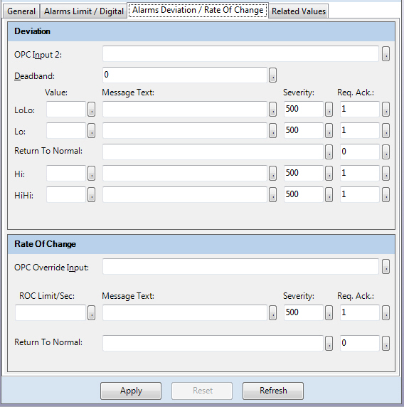
Use the Deviation pane at the top of the Alarms Deviation/Rate of Change tab of the Alarm Server Source.
-
The OPC Input 2 field is mandatory (making it different than the OPC Input field for other types of alarms). The tag you put in the OPC Input 2 field is used to calculate the deviation from the OPC Input base field. The alarm is triggered if the difference between two input values exceeds the high or low limits specified in the Alarm Server configuration. Supporting information is provided in OPC Alarm and Event Data.
-
In the Deadband field, specify a buffer amount surrounding a limit in which the alarm will not signal. The deadband value applies to converted analog values. The deadband value is required and is calculated on borderline alarming limit values to prevent repeated alarm cycles. An alarm series with a threshold of 101 (when the alarm triggers) and a deadband of +/-1 or 2 triggers in the instances with the alarm icon. Click here to see an example.
-
As needed, enter values in the Value fields of LoLo, Lo, Hi, and/or HiHi. Use these fields to provide the acceptable limits of deviation between the two tags' readings. (Note that you are not entering the value of a tag. Instead, you are entering the difference in value between two tags.) You can set one, two, three, or four limits, each with its own warning or alert text, severity level, and acknowledgement requirements. The alarm's appearance when it is triggered during runtime is configured when the alarm tag is added to an alarm grid, as described in Grid Options in an AlarmWorX64 Viewer.
-
-
HiHi: Triggers an alarm if the value is greater than or equal to the HiHi limit specified in the Alarm Server configuration.
-
Hi: Triggers an alarm if the value is greater than or equal to the Hi limit specified in the Alarm Server configuration.
-
Lo: Triggers an alarm if the value is greater than or equal to the Lo limit specified in the Alarm Server configuration.
-
LoLo: Triggers an alarm if the value is greater than or equal to the LoLo limit specified in the Alarm Server configuration.
-
Normal State: If the value is less than the LoLo limit specified in the Alarm Server configuration.
The values that you enter are compared to readings from the tag. For example, a value of 10 for LoLo is compared with the value of the OPC tag to determine if the alarm is in LoLo state. The alarm is triggered when the OPC tag's value exceeds the high or low limits.
-
For each Value field (LoLo, Lo, Hi, HiHi) that you are using, specify the following information:
-
|
|
Note: If you don't specify message text, by default the OPC subcondition name and the OPC condition name are used. For example, a LoLo alarm will post a description of LoLo limit.
|
-
-
Severity is the OPC-defined value for the alarm's priority. The valid OPC severity range is 0 (lowest) to 1000 (highest). For more about severity codes, refer to the Error Reporting table.
-
Requires Ack determines whether the alarm requires a user's acknowledgement. If the condition requires user acknowledgement, enter 1. If it doesn't require acknowledgement, enter 0; when the range returns to normal, the alarm will be posted as already acknowledged. For more information, refer to Alarm Acknowledgement.
- Next to Return to Normal, specify the text that appears when the tag's value returns to within normal bounds from an alarm condition. Values between the Lo and Hi limit, exclusively, are considered normal. The message can be any text string, including a language alias (Unicode version only). Also specify if the runtime operator is required to acknowledge a return to normal; enter 1 or 0, as described above in step 5.
|
|
Note: Changes to the alarm property fields (HiHi, LoLo, Hi, Lo, Message Text, etc.) made in runtime through an OPC tag update are automatically saved to the database and overwrite any values specified in configuration mode.
|
Return to Alarm Tags or Alarm Tag Templates
Rate of Change Alarms
The Rate of Change alarm occurs when the rate of change in the OPC tag's values is more severe than allowed by the alarm's configuration. The rate of change is calculated by taking the difference between the last two OPC values and using their timestamps to calculate the rate of change per second. For example, the value -1 is returned, then .5 seconds later a value of 1 is returned for a difference of 2. The difference is applied to an entire second, therefore the rate of change per second is 4. Then .5 seconds later a value of -1 is returned for a half-second difference of 2, again; the rate of change is 4 again. If the alarm's limit is set to 5, neither of these rates of change reports an alarm, but if the alarm's limit is set to 2, both result in an alarm being reported.
The rate is measured in terms of a delta between the last two values received; no positive or negative limits can be provided. (To be able to measure the difference in terms of positive or negative changes, use the Rate Limit alarm, described below.)
To configure a Rate of Change alarm for the OPC tag, follow these steps:
-
Use the Rate of Change pane at the bottom of the Alarms Deviation/Rate of Change tab.
-
By default, this alarm reads the values of the OPC tag you specified in the OPC Input field. You can overwrite this tag by specifying a different tag in the OPC Override Input field in the Rate of Change pane.
-
In the ROC Limit/Sec field, specify the rate of change per second that must trigger the alarm. For example, you can set up a Rate of Change alarm so that if the water level drops more than 2 centimeters per second, the alarm will report.
-
Next to the ROC Limit/Sec field, specify the following:
-
-
Message Text is the warning message that will appear when the alarm is set. The message can be any text string, including a language alias (Unicode version only).
-
Severity is the OPC-defined value for the alarm's priority. The valid OPC severity range is 0 (lowest) to 1000 (highest). For more about severity codes, refer to the Error Reporting table.
-
Requires Ack determines whether the alarm requires a user's acknowledgement. If the condition requires user acknowledgement, enter 1. If it doesn't require acknowledgement, enter 0; when the range returns to normal, the alarm will be posted as already acknowledged. For more information, refer to Alarm Acknowledgement.
-
Next to Return to Normal field, specify the message to display when the alarm returns to normal. Also specify if the runtime operator is required to acknowledge a return to normal; enter 1 or 0, as described above in step 4.
Return to Alarm Tags or Alarm Tag Templates
Rate Limit Alarms
A Rate Limit alarm is much like the Rate of Change alarm except that the change is not an absolute number; it is expressed in terms of a positive or negative value. The rate of change is calculated per second by taking the increase or decrease in value of the last two OPC values; using the two values' timestamps, the increase or decrease over the length of a second (that is, the rate) is calculated, then compared to the high and/or low limits defined in the alarm tag. If the rate exceeds one of the limits, the alarm reports.
The rate is measured as a real number, not as the rate's absolute. This lets you set LoLo, Lo, Hi, and HiHi limits for the alarm. (In contrast, the Rate of Change alarm, described above, measures the rate as an absolute value with one limit that can be set.) For example, the value -1 is returned, then .5 seconds later a value of 1 is returned for a difference of +2. The difference is applied to an entire second, therefore the rate of change per second is +4. The alarm's Hi limit is set to 5, so no alarm is reported. Then .5 seconds later a value of -1 is returned for a half-second difference of -2, making the rate of change per second -4. The alarm's Lo limit is set to -2, so an alarm is reported.
To create a Rate Limit alarm for the OPC tag, follow these steps:
-
Use the Rate Limit (RLM) pane at the bottom of the Alarms Rate Limit/Trigger Limit tab.
-
By default, this alarm reads the values of the OPC tag you specified in the OPC Input field. You can overwrite this tag by specifying a different tag in the OPC Override Input field in the Rate Limit pane.
-
In the Deadband field, specify a buffer amount surrounding a limit in which the alarm will not signal. The deadband value applies to converted analog values. The deadband value is required and is calculated on borderline alarming limit values to prevent repeated alarm cycles. An alarm series with a threshold of 101 (when the alarm triggers) and a deadband of +/-1 or 2 triggers in the instances with the alarm icon. Click here to see an example.
-
As needed, enter values in the Value fields of LoLo, Lo, Hi, and/or HiHi. Use these fields to provide the acceptable limits of the tag’s rate of change. You can set one, two, three, or four limits, each with its own warning or alert text, severity level, and acknowledgement requirements. The alarm's appearance when it is triggered during runtime is configured when the alarm tag is added to an alarm grid, as described in Grid Options in an AlarmWorX64 Viewer.
-
HiHi: Triggers an alarm if the value is greater than or equal to the HiHi limit specified in the Alarm Server configuration.
-
Hi: Triggers an alarm if the value is greater than or equal to the Hi limit specified in the Alarm Server configuration.
-
Lo: Triggers an alarm if the value is less than or equal to the Lo limit specified in the Alarm Server configuration.
-
LoLo: Triggers an alarm if the value is less than or equal to the LoLo limit specified in the Alarm Server configuration.
The values that you enter are compared to the rate. The alarm is triggered when the OPC tag's rate exceeds the high or low limits.
-
For each Value field (LoLo, Lo, Hi, HiHi) that you are using, specify the following information:
-
|
|
Note: If you don't specify message text, by default the OPC subcondition name and the OPC condition name are used. For example, a LoLo alarm will post a description of LoLo limit.
|
-
-
Severity is the OPC-defined value for the alarm's priority. The valid OPC severity range is 0 (lowest) to 1000 (highest). For more about severity codes, refer to the Error Reporting table.
-
Requires Ack determines whether the alarm requires a user's acknowledgement. If the condition requires user acknowledgement, enter 1. If it doesn't require acknowledgement, enter 0; when the range returns to normal, the alarm will be posted as already acknowledged. For more information, refer to Alarm Acknowledgement.
- Next to Return to Normal, specify the text that appears when the tag's rate returns to within normal bounds from an alarm condition. Values between the Lo and Hi limit, exclusively, are considered normal. The message can be any text string, including a language alias (Unicode version only). Also specify if the runtime operator is required to acknowledge a return to normal; enter 1 or 0, as described above in step 5.
|
|
Note: Changes to the alarm property fields (HiHi, LoLo, Hi, Lo, Message Text, etc.) made in runtime through an OPC tag update are automatically saved to the database and overwrite any values specified in configuration mode.
|
Return to Alarm Tags or Alarm Tag Templates
Trigger Limit Alarms
The Trigger Limit alarm reports when the OPC tag's value changes and requires a runtime operator's acknowledgement. This type of alarm is useful for an OPC tag whose value rarely changes, such as tag that reports a state. When the value changes, the alarm will report and will not reset until after a runtime operator acknowledges it. With this alarm, there is no normal condition; any change in the value triggers the alarm.
To configure a Trigger Limit alarm for the OPC tag, follow these steps:
-
Use the Trigger Limit (TLA) pane at the bottom of the Alarms Rate Limit/Trigger Limit tab.
-
By default, this alarm reads the values of the OPC tag you specified in the OPC Input field. You can overwrite this tag by specifying a different tag in the OPC Override Input field in the Trigger Limit (TLA) pane.
-
To activate the alarm, put a check mark in the Enable check box.
-
Next to the Enable check box, specify the following:
-
-
Message Text is the warning message that will appear when the alarm reports. The message can be any text string, including a language alias (Unicode version only).
-
Severity is the OPC-defined value for the alarm's priority. The valid OPC severity range is 0 (lowest) to 1000 (highest). For more about severity codes, refer to the Error Reporting table.
-
Req. Ack. determines that the alarm requires a user's acknowledgement. Because by definition this alarm requires acknowledgement, 1 is the only value you should be entering in this field. Although you can enter other values, no other value is supported at this time. For more information, refer to Alarm Acknowledgement.
-
Delay (seconds) delays alarm reporting. If the alarm condition still exists after this delay, the alarm is reported. Normally, alarms are reported as soon as they are detected.
-
Heart Beat - this option requires use of Delay (seconds) to control the delay before reporting an alarm. A Heart Beat alarm is triggered when the current value equals the last update value.
Return to Alarm Tags or Alarm Tag Templates
Related Values
The last tab found on the AlarmWorX64 Server Tag form is the Related Values tab. Related values stores the condition of values at the time an alarm was triggered. Use it to capture alarm-related conditions to help diagnose the problem at a later date. Related values can be the value of an OPC data access item, a static string, an expression, or a constant expression. This is often used to identify the alarm condition with a particular lot or batch.
The Related Values tab provides an association between up to 20 OPC tags or expressions that you specify with each alarm tag. When an alarm triggers the related values tag can be use to store the conditions of that applied that the time the alarm went off. Consider a production process with an overall quality tag that triggers an alarm indicating that the quality has dropped below a certain value. The alarm by itself does little to tell the operator why the alarm triggered, and more importantly how to fix the error condition. Using related values it is possible to store the information from up to twenty sensors or devices that make the error's cause more clear.
For example, when a company runs a chocolate chip cookie production line and gets an alarm that the cookies are burnt, sensors can tell the operator if this is because the oven temperature is too high, the speed through the oven is too low, or some other related factor. The supplemental or related values become part of the permanent alarm record and are stored along with the alarm information. You can choose OPC tags and expressions for the various fields by clicking the arrow buttons.
Supporting information is provided in OPC Alarm and Event Data.
Return to Alarm Tags or Alarm Tag Templates