![]()
![]()
In this quick start, you will learn some of the basics of BridgeWorX64 by walking through the configuration of a simple transaction.
BridgeWorX can be found inside of Workbench under Bridging.
Bridging Node in Workbench
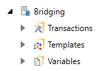
It will contain three main sections: Transactions (where you can configure properties such as priority, retry delay, and timeouts), Templates (where you can configure a diagram of your desired scenario), and Variables (where you can declare values to be used in transaction diagrams).
BridgeWorX64 transactions can contain these types of activities:
Start, End
Readers
Writers
Manipulators
Conditions
All BridgeWorX64 transactions will begin at the Start activity when triggered for execution. From there they will proceed through some number of activities as configured, and will terminate at an End block.
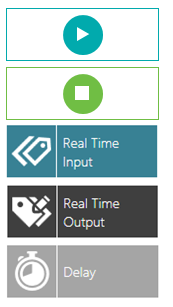
The following image shows the different activities we will use in this Help topic.
Used Activities
The application note will give you an example of how to retrieve an OPC value and move it to another OPC tag. After 10 seconds the OPC tag will be set to 0 again.
Under Bridging, right-click on Transactions and then on Add Configuration.
Name your configuration NorthwindTest and check the box for Active Configuration.
Click on the Browse  icon next to the Temporary Directory. In the Browse for Folder dialog, select a folder to store temporary files generated and used during the transaction.
Click Apply. Right click on NorthwindTest and select Add Transaction. Name this transaction, SIMtoOPC.
Check The transaction is enabled.
Click on the + icon next to Selected Template towards the bottom of the page. This will create a new template named SIMtoOPC.
Open the Template Designer by clicking on the  icon to the left of the + icon.
In the Template Diagram tab, we can easily select activities and drag and drop them to create a diagram.
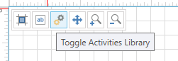
If the Activities Library is not visible, click on the Toggle Activities Library icon in the grid, as pictured in the following image. This should open the Activity Library on the left.
Toggle Activities Library
The first Activity in the diagram editor will indicate the start of our diagram.
Start Activity

Drag the Real Time Input activity onto the diagram. The Start activity should automatically connect to the Real Time Input activity.
Make sure the Real Time Input activity is selected. You should see its details to the right of your diagram. Name your activity Read OPC.
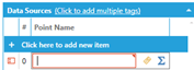
Scroll down to the Data Sources panel. Click to add a tag, and then browse for My Computer > Data Connectivity > OPC Data Access > Simulations > Double > Sine.
Browsing for Tags Icon
Now, add a Real Time Output activity. This will take the value from the previous activity and write it to another data source. Name it R/W stream.
Scroll down to the Data Sources dialog, add a new item, and browse for a point. Browse for My Computer > Data Connectivity > OPC Data Access > Simulations > Double > Static.
To the right of our newly mapped tag, click in the Output Expression cell, then on the ∑ icon, to open the expression editor. Clear out the existing expression, then on the left side, double-click on Previous Activity Output. Change Col[indexOrName] to Col[1] and Row[index] to Row[0]. This means we are copying the first row, second column of the dataset from our previous activity. Click OK to the expression editor.
Edit the Expression
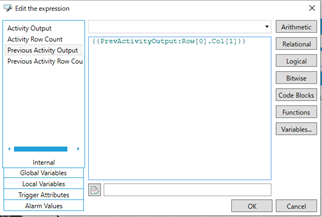
NOTE: You may wonder why we are taking Col[1] instead of Col[0]. Every Input activity in BridgeWorX64 returns a dataset, including the Real Time Input block. This is true even when the input block only has one tag. The first column (Col[0]) is the point name, and the second column (Col[1]) is the point value. You can see the column definitions for an input block by selecting that block and looking at to the Data Schema section. You’ll see for the Read OPC block that column 0 is PointName and column 1 is Value.
Add a Delay action to your diagram. Name it, Delay 10s, and change the delay to 10,000 milliseconds.
Next, add another Real Time Output Activity, and name it Write 0. In its Data Sources field, add the same simulator tag as the last output activity:
(@sim64:Double.Static("Static1").Value). In Output Expression, put, x=0.
Add the End Activity to the diagram.
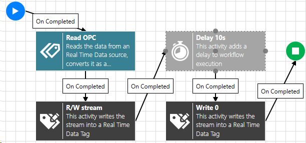
To finish our scenario, connect the End Activity to our diagram. Right-click our Write 0 activity to add a completed link. Drag this link to our previously added End Activity. Our diagram should look like the following image.
Final Diagram
Apply your changes to the diagram and the transaction.
1. Open GraphWorX64.
2. Add these three process points into your display, and add these text labels next to them:
|
Point |
Label |
|
@sim64:Double.Sine(Period[sec], Min,Max,Phase[deg]).Value |
SQL Value |
|
@sim64:Double.Static("Static1").Value |
Simulated Value |
|
bwx:SIMtoOPC/@@Execute |
Start Transaction |
NOTE: You should be able to browse for the last tag under My Computer > Bridging > SIMtoOPC > @@Execute.
3. Make sure that DataEntry is set to True for the @@Execute point.
4. Go into runtime.
5. Write a 1 to the Start Transaction point. You should see the SQL value be copied into the simulated value, then 10 seconds later it should return to zero.
See Also: