This topic describes how to create a sliding mechanism to be used as input that writes to an OPC tag.
Open the Sliders symbol library in the Miscellaneous folder and drag Slider 01 to the design surface.
Double-click the Grouped shape until you select the central red rectangle.
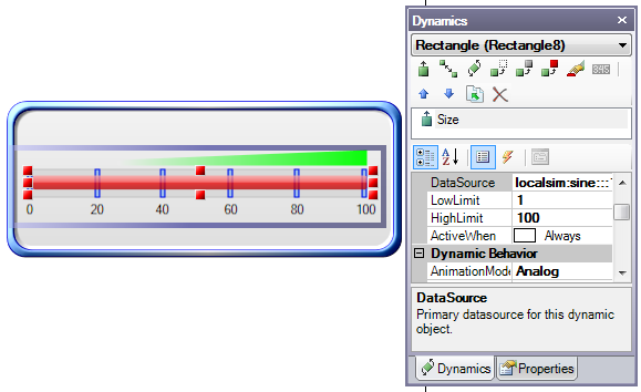
Select the Size dynamic and set the DataSource to localsim::var1 from its default value of localsim:sine:::1:100 as shown in the figure below.
Slider 1 with the Size Dynamic for the Central Indicator Rectangle Chosen

Create a small rectangle that is the size of a slider and add it to the Slider group and move it to the 0 point of Slider 01.
With the slider control you just created selected click on the Location dynamic and then drag the red arrow and rectangle outline so that the second rectangle is located over the 100 point of Slider 01. Your figure should look something like the figure below.
Slider 01 with the Slider Dynamic Shown Below

Move the slider over the 0 position as is shown in the figure above, then select the properties AnimationMode to Analog and Slider to True.
Click on the Process Point tool in the Text Objects tab group, click on the design surface to create the Process Point object; then set the DataSource of that object to localsim::var1.
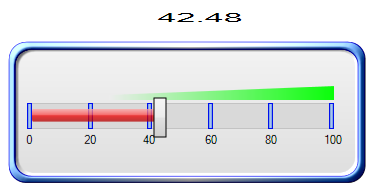
Go into runtime and then move the Slider control left and right. You will see the value in the process point change from 0 to 100 depending on the position of the control. The figure below shows the final state of the Slider.
The Slider Control with Process Point

See also:
Dynamics in the GraphWorX64 Interface